Mitsubishi Eclipse / Eclipse Spyder (2000-2002). Service and repair manual — part 152
MULTIPORT FUEL INJECTION (MFI) DIAGNOSIS
TSB Revision
MULTIPORT FUEL INJECTION (MFI) <2.4L ENGINE>
13A-307
STEP 14. Test the OBD-II drive cycle.
(1) Carry out a test drive with the drive cycle pattern. Refer to,
Procedure 6
−
Other Monitor (
).
(2) Check the diagnostic trouble code (DTC).
Q: Is the DTC P0507 is output?
YES : Retry the troubleshooting.
NO : The inspection is complete.
DTC P0551: Power Steering Pressure Sensor Circuit Range/Performance
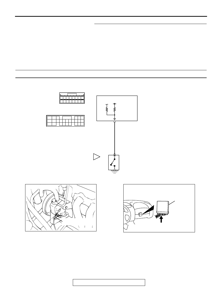
CIRCUIT OPERATION
•
A battery positive voltage is applied to the power
steering pressure switch output terminal (terminal
1) from the ECM (terminal 37) or PCM (terminal
52) <A/T> via the resistor in the ECM <M/T> or
PCM <A/T>.
TECHNICAL DESCRIPTION
•
The power steering pressure switch converts the
existence of a power steering load into a high/low
voltage, and inputs it into the ECM <M/T> or
PCM <A/T>.
AK000670
34
33
32
36
35
37
42
45
31
39
38
46
40 41
1
43 44
YELLO
W
ENGINE CONTROL
MODULE(ECM)<M/T>
OR
POWERTRAIN CONTROL
MODULE(PCM)<A/T>
C-53<M/T>
(MU803771)
C-54<A/T>
(MU803781)
37<M/T>
52<A/T>
POWER STEERING
PRESSURE SWITCH
B-19
1
42 43
48 49 50 51 52 53 54 55 56 57
46
45
44
58 59
60 61 62 63
64 65 66
47
41
ACX02520
CONNECTOR : B-19
POWER STEERING
PRESSURE SWITCH
AD
AK000280
C-53,C-54
ECM<M/T>
OR
PCM<A/T>
CONNECTORS:C-53<M/T>,C-54<A/T>
BH
MULTIPORT FUEL INJECTION (MFI) DIAGNOSIS
TSB Revision
MULTIPORT FUEL INJECTION (MFI) <2.4L ENGINE>
13A-308
•
When the steering wheel is turned, hydraulic
pressure rises. The power steering pressure
switch closes, and the applied battery positive
voltage will be grounded. With this, the power
steering pressure switch output voltage will
fluctuate between 12 volts and 0 volt.
•
While driving with the steering wheel held
straight, the power steering pressure switch turns
"OFF."
•
The ECM <M/T> or PCM <A/T> checks whether
the power steering pressure switch turns "OFF"
or "ON" during driving.
DTC SET CONDITIONS
Check Conditions
•
Intake air temperature is higher than -10
°
C (14
°
F).
•
Barometric pressure is higher than 76 kPa (11
psi).
•
Engine coolant temperature is higher than 30
°
C
(86
°
F).
•
Drive for four seconds or more with the engine
speed at 2,500 r/min or more, the volumetric
efficiency at 55 percent or more, and vehicle
speed is 5 km/h (3.1 mph) or more. Stop the
vehicle [vehicle speed is 1.5 km/h (0.93 mph) or
less]. Repeat 10 times or more.
Judgment Criteria
•
Power steering pressure switch continues to be
"ON."
TROUBLESHOOTING HINTS (The most likely
causes for this code to be set are:)
•
Power steering pressure switch failed.
•
Open or shorted power steering pressure switch
circuit, or loose connector.
•
ECM failed. <M/T>
•
PCM failed. <A/T>
DIAGNOSIS
Required Special Tools
MB991502: Scan Tool (MUT-II)
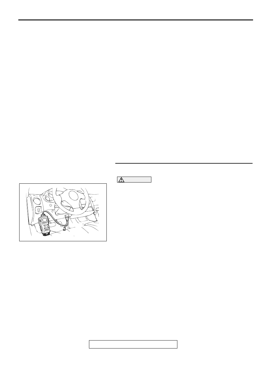
STEP 1. Using scan tool MB991502, check data list item 27:
Power Steering Pressure Switch.
CAUTION
To prevent damage to scan tool MB991502, always turn the
ignition switch to the "LOCK" (OFF) position before
connecting or disconnecting scan tool MB991502.
(1) Connect scan tool MB991502 to the data link connector.
(2) Start the engine and run at idle.
(3) Set scan tool MB991502 to the data reading mode for item
27, Power Steering Pressure Switch.
•
If the steering wheel is stopped while idling, "OFF" will
be displayed.
•
If the steering wheel is steered while idling, "ON" will be
displayed.
(4) Turn the ignition switch to the "LOCK" (OFF) position.
Q: Is the sensor operating properly?
YES : It can be assumed that this malfunction is intermittent.
Refer to GROUP 00, How to Use Troubleshooting/
Inspection Service Points (
NO : Go to Step 2.
AKX01177
16 PIN
MB991502
AB
MULTIPORT FUEL INJECTION (MFI) DIAGNOSIS
TSB Revision
MULTIPORT FUEL INJECTION (MFI) <2.4L ENGINE>
13A-309
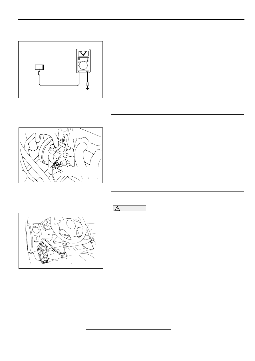
STEP 2. Check the power supply voltage at power steering
pressure switch connector B-19 by backprobing
(1) Do not disconnect the connector B-19.
(2) Start the engine and run at idle.
(3) Measure the voltage between terminal 1 and ground by
backprobing.
•
When steering wheel is stationary, voltage should be
battery positive voltage.
•
When steering wheel is turned, voltage should be 1 volt
or less.
(4) Turn the ignition switch to the "LOCK" (OFF) position.
Q: Is the voltage normal?
YES : Go to Step 3.
NO : Go to Step 5.
STEP 3. Check connector B-19 at power steering pressure
switch for damage.
Q: Is the connector in good condition?
YES : Go to Step 4.
NO : Repair or replace it. Refer to GROUP 00E, Harness
Connector Inspection (
). Then go to Step 14.
STEP 4. Using scan tool MB991502, check data list item 27:
Power Steering Pressure Switch.
CAUTION
To prevent damage to scan tool MB991502, always turn the
ignition switch to the "LOCK" (OFF) position before
connecting or disconnecting scan tool MB991502.
(1) Connect scan tool MB991502 to the data link connector.
(2) Start the engine and run at idle.
(3) Set scan tool MB991502 to the data reading mode for item
27, Power Steering Pressure Switch.
•
If the steering wheel is stopped while idling, "OFF" will
be displayed.
•
If the steering wheel is steered while idling, "ON" will be
displayed.
(4) Turn the ignition switch to the "LOCK" (OFF) position.
Q: Is the sensor operating properly?
YES : It can be assumed that this malfunction is intermittent.
Refer to GROUP 00, How to Use Troubleshooting/
Inspection Service Points (
NO : Replace the ECM or PCM. Then go to Step 14.
AK000259AB
1
B-19 CONNECTOR
HARNESS
SIDE VIEW
ACX02520
CONNECTOR : B-19
POWER STEERING
PRESSURE SWITCH
AD
AKX01177
16 PIN
MB991502
AB
MULTIPORT FUEL INJECTION (MFI) DIAGNOSIS
TSB Revision
MULTIPORT FUEL INJECTION (MFI) <2.4L ENGINE>
13A-310
STEP 5. Check connector B-19 at power steering pressure
switch for damage.
Q: Is the connector in good condition?
YES : Go to Step 6.
NO : Repair or replace it. Refer to GROUP 00E, Harness
Connector Inspection (
). Then go to Step 14.
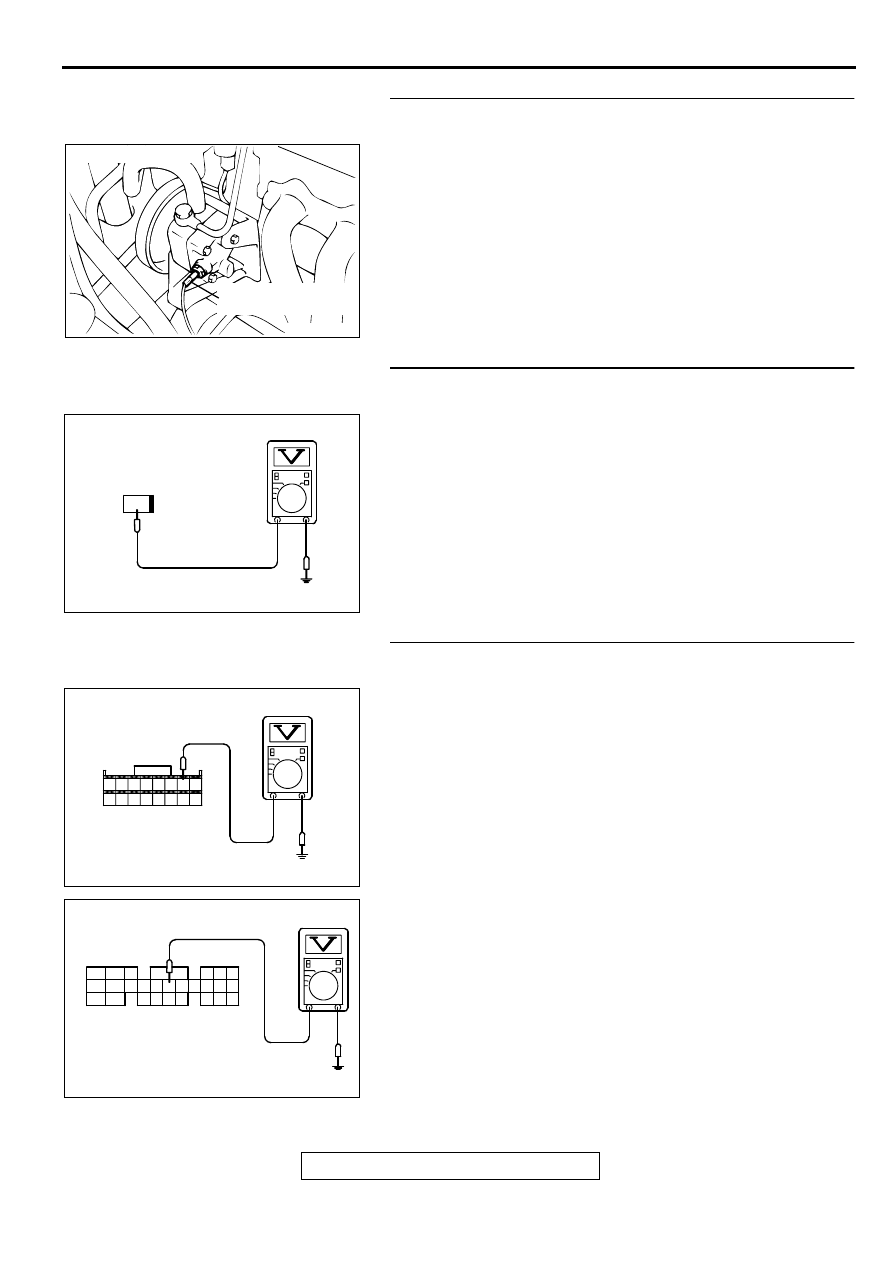
STEP 6. Check the power supply voltage at power steering
pressure switch harness side connector B-19.
(1) Disconnect the connector B-19 and measure at the harness
side.
(2) Turn the ignition switch to the "ON" position.
(3) Measure the voltage between terminal 1 and ground.
•
Voltage should be battery positive voltage.
(4) Turn the ignition switch to the "LOCK" (OFF) position.
Q: Is the voltage normal?
YES : Go to Step 11.
NO : Go to Step 7.
STEP 7. Check the power supply voltage at ECM connector
C-53 <M/T> or PCM connector C-54 <A/T> by backprobing
(1) Do not disconnect the ECM connector C-53 <M/T> or PCM
connector C-54 <A/T>.
(2) Disconnect the power steering pressure switch connector
B-19.
(3) Turn the ignition switch to the "ON" position.
(4) Measure the voltage between terminal 37 <M/T> or 52 <A/
T> and ground by backprobing.
•
Voltage should be between battery positive voltage.
(5) Turn the ignition switch to the "LOCK" (OFF) position.
Q: Is the voltage normal?
YES : Go to Step 8.
NO : Go to Step 9.
ACX02520
CONNECTOR : B-19
POWER STEERING
PRESSURE SWITCH
AD
AK000260AB
1
B-19 HARNESS
SIDE CONNECTOR
AK000308
3132 33 34 35 36 37 38
39 40 41 42 43 44 45 46
AC
<M/T>
C-53 CONNECTOR
HARNESS SIDE VIEW
AK000309
C-54 CONNECTOR
HARNESS SIDE VIEW
46
57
66
45
56
65
44
55
43
49
54
64
42
48
59
41
47
58
53
63
52
62
51
61
50
60
AD
<A/T>
Нет комментариевНе стесняйтесь поделиться с нами вашим ценным мнением.
Текст