Mitsubishi Eclipse / Eclipse Spyder (2000-2002). Service and repair manual — part 201
GENERAL INFORMATION
TSB Revision
MULTIPORT FUEL INJECTION (MFI) <3.0L ENGINE>
13B-3
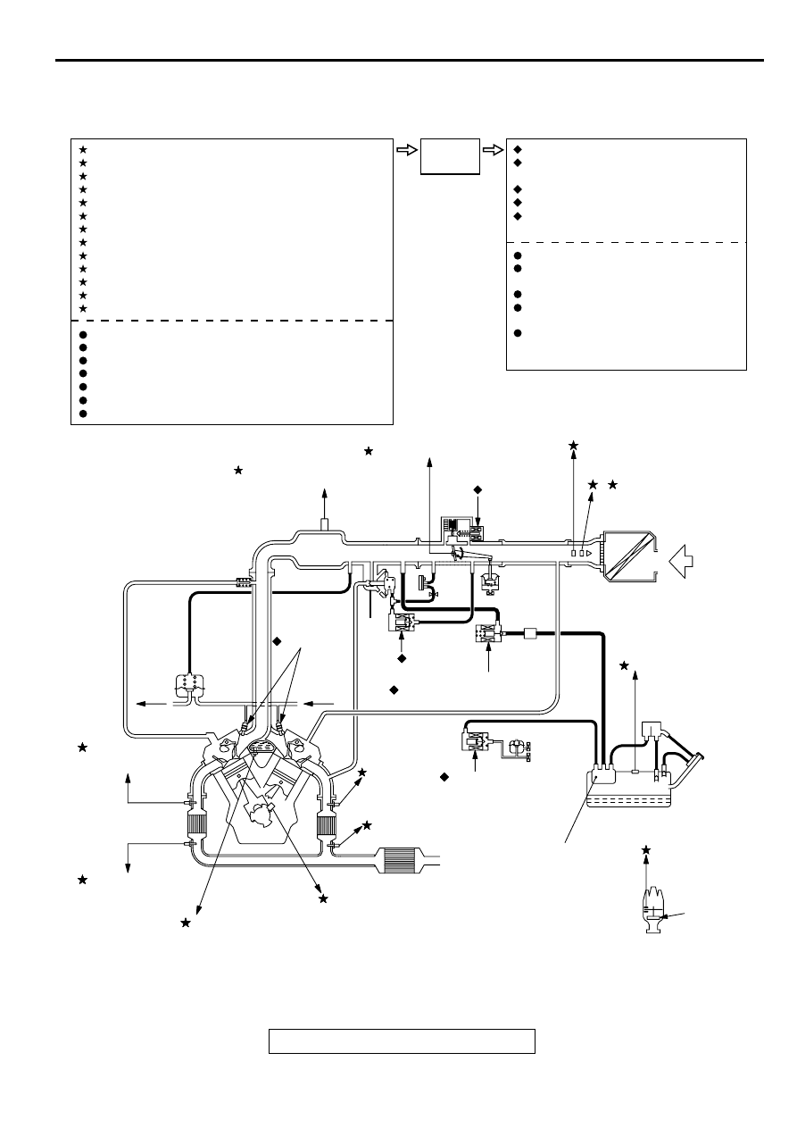
MULTIPORT FUEL INJECTION (MFI) SYSTEM DIAGRAM
NOTE: For the vacuum hose routing, refer to
GROUP 17, vacuum hoses
.
AK000045
CATALYTIC CONVERTER
FUEL PRESSURE
REGULATOR
M*1
*2
M*1
EGR
VALVE
DASH
POT
<M/T>
FROM
FUEL
PUMP
TO
FUEL
TANK
1 LEFT BANK HEATED OXYGEN SENSOR (FRONT)
2 VOLUME AIR FLOW SENSOR
3 INTAKE AIR TEMPERATURE SENSOR
4 THROTTLE POSITION SENSOR
5 CAMSHAFT POSITION SENSOR
6 CRANKSHAFT POSITION SENSOR
7 BAROMETRIC PRESSURE SENSOR
8 ENGINE COOLANT TEMPERATURE SENSOR
9 LEFT BANK HEATED OXYGEN SENSOR (REAR)
10 RIGHT BANK HEATED OXYGEN SENSOR (FRONT)
11 RIGHT BANK HEATED OXYGEN SENSOR (REAR)
12 MANIFOLD DIFFERENTIAL PRESSURE SENSOR
13 FUEL TANK DIFFERENTIAL PRESSURE SENSOR
POWER SUPPLY
VEHICLE SPEED SENSOR
A/C SWITCH
PARK/NEUTRAL POSITION SWITCH <A/T>
POWER STEERING PRESSURE SWITCH
IGNITION SWITCH - ST
KNOCK SENSOR
1 INJECTOR
2 EVAPORATIVE EMISSION
PURGE SOLENOID
3 IDLE AIR CONTROL MOTOR
4 EGR SOLENOID
5 EVAPORATIVE EMISSION
VENTILATION SOLENOID
FUEL PUMP RELAY
MULTIPORT FUEL INJECTION
(MFI) RELAY
A/C COMPRESSER CLUTCH RELAY
SERVICE ENGINE SOON/
MALFUNCTION INDICATOR LAMP
DIAGNOSTIC OUTPUT
ECM<M/T>
PCM<A/T>
SENSE
DECIDE
ACT
AB
NOTE
*1 : Manifold port
*2 : Restrictor
3 INTAKE AIR
TEMPERATURE SENSOR
2, 7
VOLUME AIR FLOW SENSOR
(WITH BAROMETRIC
PRESSURE SENSOR)
3 IDLE AIR
CONTROL
MOTOR
4 THROTTLE POSITION SENSOR
12 MANIFOLD DIFFERENTIAL
PRESSURE SENSOR
1 INJECTOR
E
CHAMBER
VCV
A
EGR
5 SOLENOID
EVAPORATIVE EMISSION
2 PURGE SOLENOID
8 ENGINE
COOLANT
TEMPERATURE
SENSOR
10 RIGHT BANK
HEATED OXYGEN
SENSOR (FRONT)
11 RIGHT BANK
HEATED OXYGEN
SENSOR (REAR)
CRANKSHAFT POSITION
SENSOR
6
9 LEFT BANK HEATED
OXYGEN SENSOR (REAR)
5 CAMSHAFT
POSITION
SENSOR
13 FUEL TANK
DIFFERENTIAL
PRESSURE SENSOR
LEFT BANK
HEATED
1 OXYGEN
SENSOR
(FRONT)
EVAPORATIVE
EMISSION
CANISTER
4 EVAPORATIVE
EMISSION
VENTILATION
SOLENOID
FUEL TANK
AIR INLET
DISTRIBUTOR
IGNITION
COIL
VENT VALVE
MULTIPORT FUEL INJECTION (MFI) DIAGNOSIS
TSB Revision
MULTIPORT FUEL INJECTION (MFI) <3.0L ENGINE>
13B-4
M U LTIPO R T FU EL IN JEC TIO N (M FI) D IA G N O SIS
TROUBLESHOOTING STRATEGY
M1131008500167
NOTE: If a DTC is erased, its "freeze frame" data will
be also erased and the readiness test status will be
reset. Store the "freeze frame" data before erasing
the DTC.
Use these steps to plan your diagnostic strategy. If
you follow them carefully, you will be sure to have
exhausted most of the possible ways to find an MFI
fault.
1. Gather as much information as possible about the
complaint from the customer.
2. Verify that the condition described by the
customer exists.
3. Check the vehicle for any MFI Diagnostic Trouble
Code (DTC).
4. If you cannot verify the condition and there are no
DTCs, the malfunction is intermittent. For
information on how to cope with intermittent
malfunctions, refer to GROUP 00, How to Use
Troubleshooting/Inspection Service Points
−
How
to cope with Intermittent Malfunction
5. If you can verify the condition but there are no
DTCs, or the system cannot communicate with
the scan tool, refer to the trouble symptom
classification table.
6. If there is a DTC, record the number of the code,
then erase the code from the memory using the
scan tool.
7. Reconfirm the malfunction symptom and carry out
a test drive with the drive cycle pattern.
8. If DTC is set again, carry out an inspection with
the inspection procedure for diagnostic trouble
codes of that code.
9. If DTC is not set again, the malfunction is
intermittent. For information on how to cope with
intermittent malfunctions, refer to GROUP 00,
How to Use Troubleshooting/Inspection Service
Points
−
How to cope with Intermittent Malfunction
10.After repairs are completed, conduct a road test
duplicating the complaint set conditions to confirm
the malfunction has been connected.
NOTE: If the engine control module (ECM) <M/T> or
powertrain control module (PCM) <A/T> is replaced,
the immobilizer-ECU should be replaced together
with it. Each ECM <M/T> or PCM <A/T> has an
individual information for immobilizer-ECU, and the
individual information is registered in the immobilizer-
ECU.
TROUBLE CODE DIAGNOSIS
M1131008600153
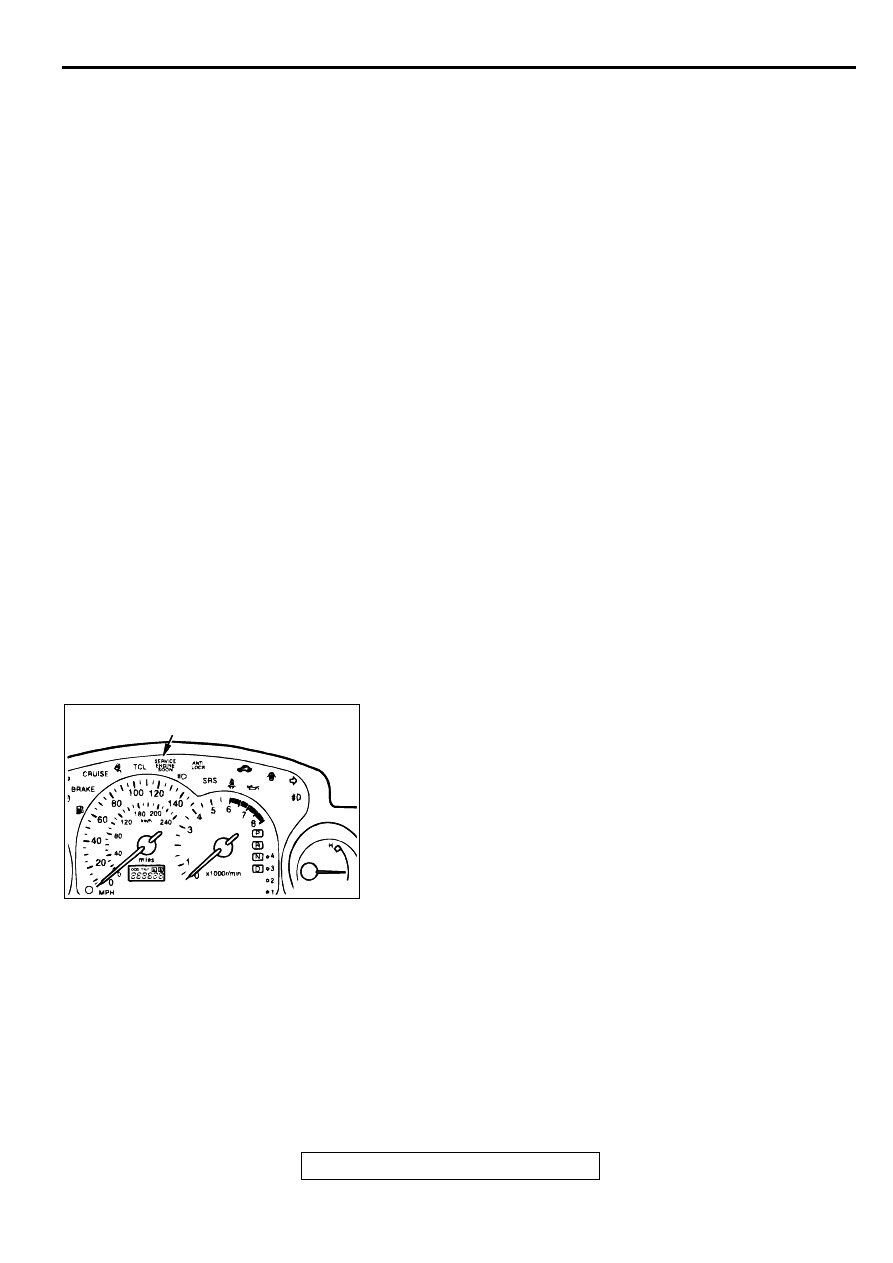
SERVICE ENGINE SOON/MALFUNCTION INDICATOR
LAMP
Among the on-board diagnostic items, a Service Engine Soon/
Malfunction Indicator Lamp illuminates to notify the driver of an
emission control malfunction.
However, when an irregular signal returns to normal and the
powertrain control module judges that it has returned to normal,
the Service Engine Soon/Malfunction Indicator Lamp is
switched off.
Moreover, when the ignition switch is turned off, the lamp is
switched off. Even if the ignition switch is turned on again, the
lamp does not illuminate until the malfunction is detected.
Immediately after the ignition switch is turned on, the Service
Engine Soon/Malfunction Indicator Lamp is lit for five seconds
to indicate that the Service Engine Soon/Malfunction Indicator
Lamp operates normally.
AK000054
AB
SERVICE ENGINE SOON/
MALFUNCTION INDICATOR LAMP

MULTIPORT FUEL INJECTION (MFI) DIAGNOSIS
TSB Revision
MULTIPORT FUEL INJECTION (MFI) <3.0L ENGINE>
13B-5
Items Indicated by the Service Engine Soon/Malfunction Indicator Lamp
DTC NO.
ITEMS
-
Engine control module (ECM) <M/T> powertrain control module (PCM) <A/T> malfunction
P0101
Volume air flow circuit range/performance problem
P0102
Volume air flow circuit low input
P0103
Volume air flow circuit high input
P0107
Barometric pressure circuit low input
P0108
Barometric pressure circuit high input
P0111
Intake air temperature circuit range/performance problem
P0115
Engine coolant temperature circuit high input
P0116
Engine coolant temperature circuit range/performance problem
P0117
Engine coolant temperature circuit low input
P0121
Throttle position circuit range/performance problem
P0122
Throttle position circuit low input
P0123
Throttle position circuit high input
P0128
Coolant thermostat malfunction
P0130
O
2
sensor circuit malfunction (bank 1 sensor 1)
P0133
O
2
sensor circuit slow response (bank 1 sensor 1)
P0134
O
2
sensor circuit no activity detected (bank 1 sensor 1)
P0135
O
2
sensor heater circuit malfunction (bank 1 sensor 1)
P0136
O
2
sensor circuit malfunction (bank 1 sensor 2)
P0139O
2
sensor circuit slow response (bank 1 sensor 2)
P0141
O
2
sensor heater circuit malfunction (bank 1 sensor 2)
P0150
O
2
sensor circuit malfunction (bank 2 sensor 1)
P0153
O
2
sensor circuit slow response (bank 2 sensor 1)
P0154
O
2
sensor circuit no activity detected (bank 2 sensor 1)
P0155
O
2
sensor heater circuit malfunction (bank 2 sensor 1)
P0156
O
2
sensor circuit malfunction (bank 2 sensor 2)
P0159O
2
sensor circuit slow response (bank 2 sensor 2)
P0161
O
2
sensor heater circuit malfunction (bank 2 sensor 2)
P0171
System too lean (bank 1)
P0172
System too rich (bank 1)
P0174
System too lean (bank 2)
P0175
System too rich (bank 2)
P201
Injector circuit malfunction
−
cylinder 1
P0202
Injector circuit malfunction
−
cylinder 2
P0203
Injector circuit malfunction
−
cylinder 3
P0204
Injector circuit malfunction
−
cylinder 4
P0205
Injector circuit malfunction
−
cylinder 5
P0206
Injector circuit malfunction
−
cylinder 6

MULTIPORT FUEL INJECTION (MFI) DIAGNOSIS
TSB Revision
MULTIPORT FUEL INJECTION (MFI) <3.0L ENGINE>
13B-6
NOTE: If the Service Engine Soon/Malfunction Indicator Lamp illuminates because of a malfunction of the
engine control module (ECM) <M/T> or powertrain control module (PCM) <A/T>, communication between
scan tool MUT-II (MB991502) and the ECM <M/T> or PCM <A/T> is impossible. In this case, the diagnostic
trouble code cannot be read.
P0300
Random misfire detected
P0301
Cylinder 1 misfire detected
P0302
Cylinder 2 misfire detected
P0303
Cylinder 3 misfire detected
P0304
Cylinder 4 misfire detected
P0305
Cylinder 5 misfire detected
P0306
Cylinder 6 misfire detected
P0335
Crankshaft position sensor circuit malfunction
P0340
Camshaft position sensor circuit malfunction
P0401
Exhaust gas recirculation flow insufficient detected
P0403
Exhaust gas recirculation solenoid malfunction
P0421
Warm up catalyst efficiency below threshold (bank 1)
P0431
Warm up catalyst efficiency below threshold (bank 2)
P0442
Evaporative emission control system leak detected
P0443
Evaporative emission control system purge control valve circuit malfunction
P0446
Evaporative emission control system vent control malfunction
P0450
Evaporative emission control system pressure sensor malfunction
P0451
Evaporative emission control system pressure sensor range/performance
P0455
Evaporative emission control system leak detected (Gross leak)
P0500
Vehicle speed sensor malfunction
P0506
Idle control system RPM lower than expected
P0507
Idle control system RPM higher than expected
P0551
Power steering pressure sensor circuit range/performance
P0705
Transmission range sensor circuit malfunction (PRNDL input)
P0710
Transmission fluid temperature sensor circuit malfunction
P0715
Input/turbine speed sensor circuit malfunction
P0720
Output speed sensor circuit malfunction
P0725
Engine speed input circuit malfunction
P0740
Torque converter clutch system malfunction
P0750
Shift solenoid A malfunction
P0755
Shift solenoid B malfunction
P0760
Shift solenoid C malfunction
P0765
Shift solenoid D malfunction
P1400
Manifold differential pressure sensor circuit malfunction
P1751
A/T control relay malfunction
DTC NO.
ITEMS
Нет комментариевНе стесняйтесь поделиться с нами вашим ценным мнением.
Текст