Mitsubishi Eclipse / Eclipse Spyder (2000-2002). Service and repair manual — part 202
MULTIPORT FUEL INJECTION (MFI) DIAGNOSIS
TSB Revision
MULTIPORT FUEL INJECTION (MFI) <3.0L ENGINE>
13B-7
NOTE: After the ECM <M/T> or PCM <A/T> has detected a malfunction, the Service Engine Soon/
Malfunction Indicator Lamp illuminates when the engine is next turned on and the same malfunction is re-
detected.
NOTE: After the Service Engine Soon/Malfunction Indicator Lamp illuminates, it will be switched off under the
following conditions.
.
•
When the ECM <M/T> or PCM <A/T> monitored the power train malfunction three times* and met set
condition requirements, it detected no malfunction. *: In this case, "one time" indicates from engine start to
stop.
•
For misfiring or a fuel trim malfunction, when driving conditions (engine speed, engine coolant
temperature, etc.) are similar to those when the malfunction was first recorded.
NOTE: Sensor 1 indicates the sensor mounted at a position closest to the engine, and sensor 2 indicates the
sensor mounted at the position second closest to the engine.
NOTE: Bank 1 indicates the right bank side cylinder, and bank 2 indicates the left bank side cylinder.
HOW TO READ AND ERASE DIAGNOSTIC
TROUBLE CODE
Refer to GROUP 13A, Trouble code diagnosis
−
How to Read
and Erase Diagnostic Trouble Codes
PROVISIONAL DTCs [MUT-II OBD-II Test Mode-
Results (Mode 5)]
Refer to GROUP 13A, Trouble code diagnosis
−
Provisional
DTCs [MUT-II OBD-II Test Mode-Results (Mode 5)]
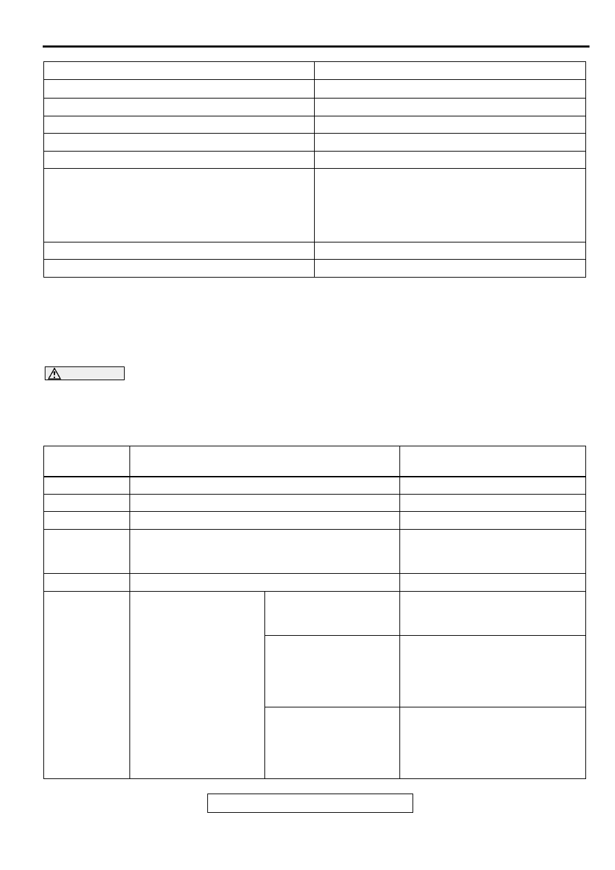
MODE 6 REFERENCE TABLE
The powertrain control module (PCM) monitors the condition of emission control system.
By selecting MODE 6 using scan tool, Test Result and Limit Value (minimum) *1 or (maximum) *2 about the
main items of emission control system which PCM monitors can be confirmed. The value at the last
monitoring is output by PCM as a test result.

MULTIPORT FUEL INJECTION (MFI) DIAGNOSIS
TSB Revision
MULTIPORT FUEL INJECTION (MFI) <3.0L ENGINE>
13B-8
NOTE: *1: The test fails if test value is less than this value.
NOTE: *2: The test fails if test value is greater than this value.
NOTE: *3: When the test result indicates the following, it means the monitoring of PCM is incomplete.
.
•
"Test incomplete." <in case of Scan tool>
•
"00" or "FF" <in case of General scan tool>
NOTE: *4: In case that the value output by General scan tool is HEX, convert them after decimalized.
DIAGNOSTIC BY DIAGNOSTIC TEST MODE II
(INCREASED SENSITIVITY)
Refer to GROUP 13A, Trouble code diagnosis
−
Diagnostic by
Diagnostic Test Mode II (Increased Sensitivity)
.
TEST
ID
MONITORING
ITEM
SIMPLE TECHNICAL DESCRIPTION
INDICATION OF
SCAN TOOL*3
CONVERSION
COEFFICIENT IN
USING
GENERAL SCAN
TOOL*4
01
Catalyst
monitor (Bank
1)
PCM monitors the deterioration of
catalyst at right bank side by the output
frequency ratio between right bank
heated oxygen sensor (front) and right
bank heated oxygen sensor (rear).
Catalyst Frequency
Ratio Bank 1
Test Result and Limit
Value (max.)
×
0.39
02
Catalyst
monitor (Bank
2)
PCM monitors the deterioration of
catalyst at left bank side by the output
frequency ratio between left bank
heated oxygen sensor (front) and left
bank heated oxygen sensor (rear).
Catalyst Frequency
Ratio Bank 2
Test Result and Limit
Value (max.)
×
0.39
03
EGR monitor
PCM monitors the operation of EGR
system by the pressure difference of
intake manifold between before and
after introduction of EGR using the
manifold differential pressure sensor.
EGR Monitor
Pressure Value
Test Result and Limit
Value (min.) kPa
×
0.43 kPa
06
Evaporation
leak monitor
(Small leak)
PCM monitors the leak of fuel
evaporation gas by the reduction of
vacuum in tank after appointed time
using the fuel tank differential pressure
sensor after making the fuel tank and
the fuel line vacuum.
EVAP Leak Mon.
1mm Pressure Value
Test Result and Limit
Value (max.) Pa
×
0.065 Pa
07
Evaporation
leak monitor
(Large leak)
PCM monitors the leak of fuel
evaporation gas by the reduction of
vacuum in tank after appointed time
using the fuel tank differential pressure
sensor after making the fuel tank and
the fuel line vacuum.
EVAP Leak Mon.
Gross Pressure
Value
Test Result and Limit
Value (max.) Pa
×
0.065 Pa
MULTIPORT FUEL INJECTION (MFI) DIAGNOSIS
TSB Revision
MULTIPORT FUEL INJECTION (MFI) <3.0L ENGINE>
13B-9
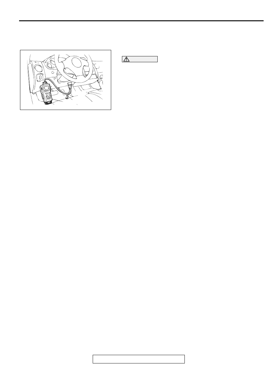
INSPECTION USING SCAN TOOL MB991502,
DATA LIST AND ACTUATOR TESTING
Required Special Tool:
MB991502: Scan Tool (MUT-II)
CAUTION
To prevent damage to scan tool MB991502, always turn the
ignition switch to the "LOCK" (OFF) position before
connecting or disconnecting scan tool MB991502.
1. Connect scan tool MB991502 to the data link connector.
2. Turn the ignition switch to the "ON" position.
3. Carry out inspection by means of the data list and the
actuator test function. If there is an abnormality, check and
repair the chassis harnesses and components. Refer to
Data List Reference Table (
). Refer to Actuator
Test Reference Table (
).
4. Re-check using scan tool MB991502 and check to be sure
that the abnormal input and output have returned to normal
because of the repairs.
5. Erase the diagnostic trouble code(s).
6. Turn the ignition switch to the "LOCK" (OFF) position.
7. Disconnect scan tool MB991502 from the data link
connector.
8. Start the engine again and do a test drive to confirm that the
problem is eliminated.
ON-BOARD DIAGNOSTICS
The engine control module (ECM) <M/T> or powertrain control module (PCM) <A/T> monitors the input/
output signals (some signals all the time and others under specified conditions) of the ECM <M/T> or PCM
<A/T>. When a malfunction continues for a specified time or longer after the irregular signal is initially
monitored, the ECM <M/T> or PCM <A/T> judges that a malfunction has occurred. After the ECM <M/T> or
PCM <A/T> first detects a malfunction, a diagnostic trouble code is recorded when the engine is restarted
and the same malfunction is re-detected. However, for items marked with a "*," a diagnostic trouble code is
recorded on the first detection of the malfunction. There are 61 diagnostic items. The diagnostic results can
be read out with a scan tool. Since memorization of the diagnostic trouble codes is backed up directly by the
battery, the diagnostic results are memorized even if the ignition key is turned off. The diagnostic trouble
codes will, however, be erased when the battery terminal or the ECM <M/T> or PCM <A/T> connector is
disconnected. In addition, the diagnostic trouble code can also be erased by turning the ignition switch to ON
and sending the diagnostic trouble code erase signal from scan tool MUT-II (MB991502) to the ECM <M/T>
or PCM <A/T>.
NOTE: If the sensor connector is disconnected with the ignition switch turned on, the diagnostic trouble code
is memorized. In this case, send the diagnostic trouble code erase signal to the ECM <M/T> or PCM <A/T> in
order to erase the diagnostic memory.
The 61 diagnostic items are all indicated sequentially from the smallest code number. The ECM <M/T> or
PCM <A/T> records the engine operating condition when the diagnostic trouble code is set. This data is
called "freeze frame" data. This data can be read by using the scan tool, and can then be used in simulation
tests for troubleshooting. Data items are as follows.
AKX01177
16 PIN
MB991502
AB
MULTIPORT FUEL INJECTION (MFI) DIAGNOSIS
TSB Revision
MULTIPORT FUEL INJECTION (MFI) <3.0L ENGINE>
13B-10
OBD- II DRIVE CYCLE
All kinds of diagnostic trouble codes (DTCs) can be monitored by carrying out a test drive according to the
following six drive cycle pattern. In other words, doing such a drive regenerates any kind of trouble which
involves illuminating the Service Engine Soon/Malfunction Indicator Lamp and verifies the repair procedure
has eliminated the trouble (the Service Engine Soon/Malfunction Indicator Lamp is no longer illuminated).
CAUTION
Two technicians should always be in the vehicle when carrying out a test drive.
NOTE: Check that the diagnosis trouble code (DTC) is not output before traveling in the drive cycle pattern.
Erase the DTC if it has been output.
DRIVE CYCLE PATTERN LIST
DATA
UNIT
Engine coolant temperature
°
C or
°
F
Engine speed
r/min
Vehicle speed
km/h or mph
Long-term fuel compensation (long-term fuel trim)
%
Short-term fuel compensation (short-term fuel trim)
%
Fuel control condition
•
Open loop
•
Closed loop
•
Open loop-drive condition
•
Open loop-DTC set
•
Closed loop-O
2
(rear) failed
Calculation load value
%
Diagnostic trouble code during data recording
-
PROCEDURE
MONITOR ITEM
DIAGNOSTIC TROUBLE CODE
(DTC)
Evaporative emission control system leak monitor
P0442,P0450,P0451,P0455
Fuel trim monitor
P0171,P0172,P0174,P0175
Catalytic converter monitor
P0421,P0431
Heated oxygen sensor monitor
P0130,P0133,
P0136,P0139,P0150,P0153,P0156
,P0159
Exhaust gas recirculation (EGR) system monitor
P0401
Other monitor
Main components
P0134, P0154, P0300,P0301,
P0302, P0303, P0304, P0305,
P0306, P0506,P0507, P1400
Sensors and switches
P0101,P0102,
P0103,P0107,P0108, P0111,
P0115,
P0116,P0117,P0121,P0122,P0123,
P0335, P0340, P0551
Wire breakage and short
circuit
P0130, P0135, P0136, P0141,
P0150, P0155, P0156, P0161,
P0201, P0202, P0203, P0204,
P0205, P0206, P0403, P0443,
P0446, P1500
Нет комментариевНе стесняйтесь поделиться с нами вашим ценным мнением.
Текст