Mitsubishi Eclipse / Eclipse Spyder (2000-2002). Service and repair manual — part 471
AUTOMATIC TRANSAXLE DIAGNOSIS
TSB Revision
AUTOMATIC TRANSAXLE
23A-176
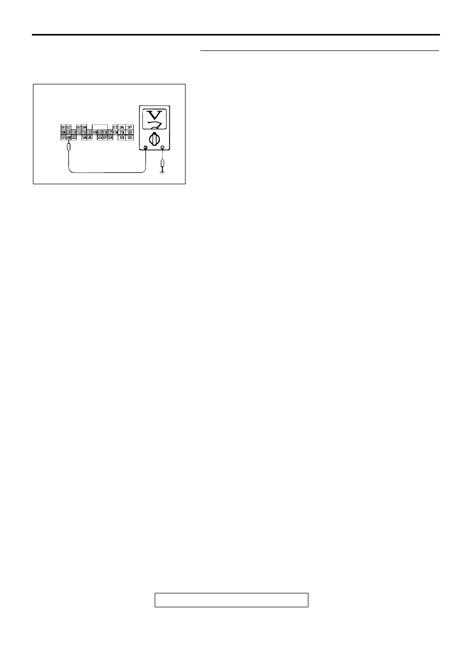
STEP 19. Check the switch output voltage at PCM
connector C-61 <2.4L Engine> or C-63 <3.0L Engine> by
backprobing. ("2" position) <Vehicles without sport mode>
Measure the voltage between terminal 122 and ground by
backprobing.
•
When selector lever position is "P," voltage should be 0.5
volt or less.
•
When selector lever position is "R," voltage should be 0.5
volt or less.
•
When selector lever position is "N," voltage should be 0.5
volt or less.
•
When selector lever position is "D," voltage should be 0.5
volt or less.
•
When selector lever position is "3," voltage should be 0.5
volt or less.
•
When selector lever position is "2," voltage should be
battery positive voltage.
•
When selector lever position is "L," voltage should be 0.5
volt or less.
Q: Is the voltage normal?
YES : Go to Step 20.
NO : Tern the ignition switch to "LOCK" (OFF) position.
Repair it because of the harness damage between
the Park/Neutral position switch connector B-41
terminal 2 and PCM connector C-61 <2.4L Engine> or
C-63 <3.0L Engine> terminal 122.
AC001908
C-61 <2.4L ENGINE> OR
C-63 <3.0L ENGINE>
CONNECTOR HARNESS
SIDE VIEW
AD
AUTOMATIC TRANSAXLE DIAGNOSIS
TSB Revision
AUTOMATIC TRANSAXLE
23A-177
STEP 20. Check the switch output voltage at PCM
connector C-61 <2.4L Engine> or C-63 <3.0L Engine> by
backprobing. ("L" position) <Vehicles without sport mode>
Measure the voltage between terminal 110 and ground by
backprobing.
•
When selector lever position is "P," voltage should be 0.5
volt or less.
•
When selector lever position is "R," voltage should be 0.5
volt or less.
•
When selector lever position is "N," voltage should be 0.5
volt or less.
•
When selector lever position is "D," voltage should be 0.5
volt or less.
•
When selector lever position is "3," voltage should be 0.5
volt or less.
•
When selector lever position is "2," voltage should be 0.5
volt or less.
•
When selector lever position is "L," voltage should be
battery positive voltage.
Q: Is the voltage normal?
YES : Go to Step 21.
NO : Tern the ignition switch to "LOCK" (OFF) position.
Repair it because of the harness damage between
the Park/Neutral position switch connector B-41
terminal 6 and PCM connector C-61 <2.4L Engine> or
C-63 <3.0L Engine> terminal 110.
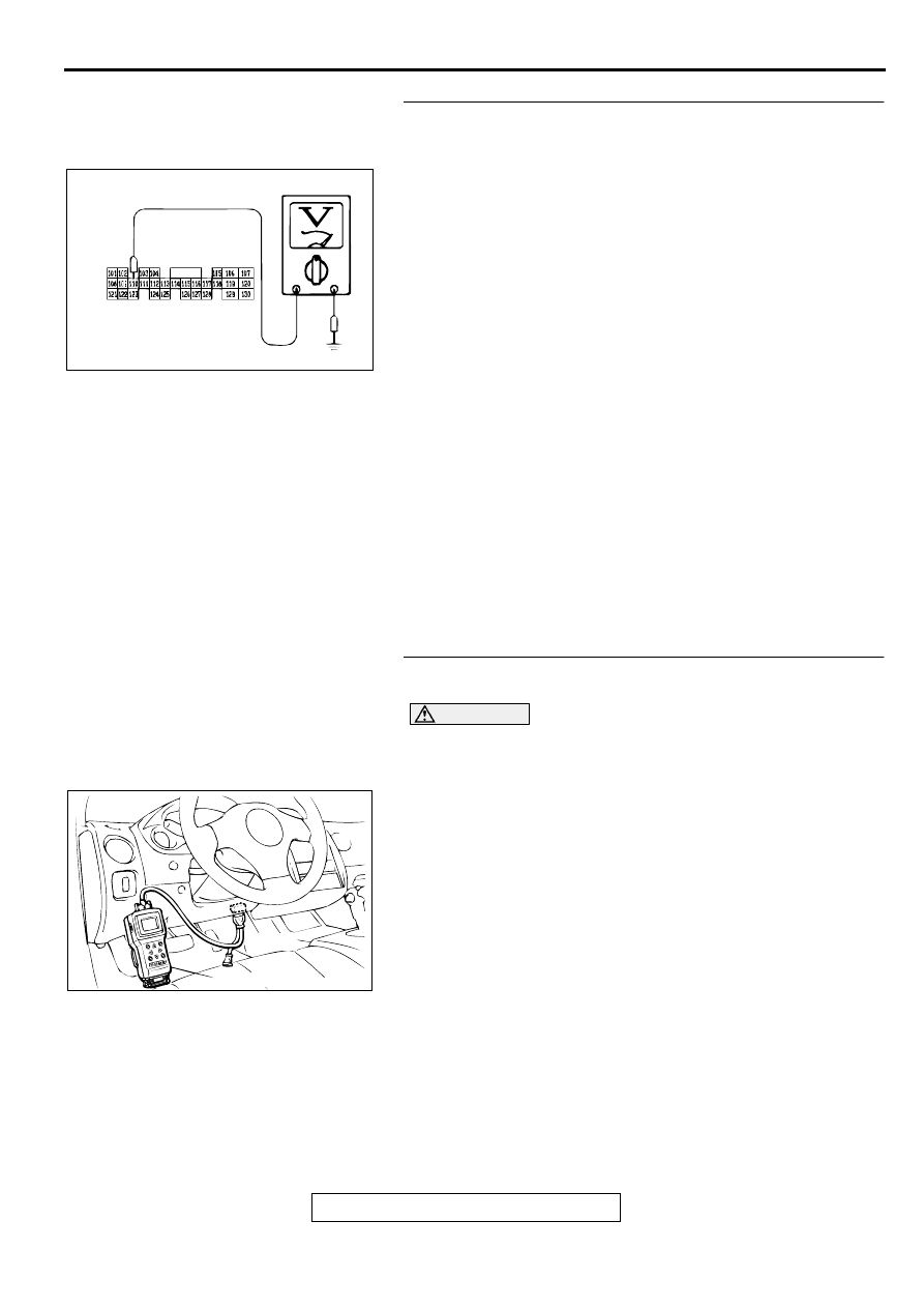
STEP 21. Using scan tool MB991502, check data list item
61: Park/Neutral Position Switch.
CAUTION
To prevent damage to scan tool MB991502, always turn the
ignition switch to "LOCK" (OFF) position before
connecting or disconnecting scan tool MB991502.
(1) Connect scan tool MB991502 to the data link connector.
(2) Turn the ignition switch to "ON" position.
(3) Set scan tool MB991502 to data reading mode for item 61:
Park/Neutral Position Switch.
•
Move the selector lever to "P," "R," "N," "D," "3," "2," "L"
and sport mode positions to confirm whether the MUT-II.
(The sport mode is indicated as "D" on the MUT-II.)
(4) Turn the ignition switch to "LOCK" (OFF) position.
Q: Is the switch operating properly?
YES : This malfunction can be intermittent. Refer to GROUP
00, How to Use Troubleshooting/Inspection Service
Points
−
How to Cope with Intermittent Malfunction
NO : Replace the PCM.
AC001946
C-61 <2.4L ENGINE> OR
C-63 <3.0L ENGINE>
CONNECTOR HARNESS
SIDE VIEW
AD
AC001252
MB991502
16 PIN
AB
AUTOMATIC TRANSAXLE DIAGNOSIS
TSB Revision
AUTOMATIC TRANSAXLE
23A-178
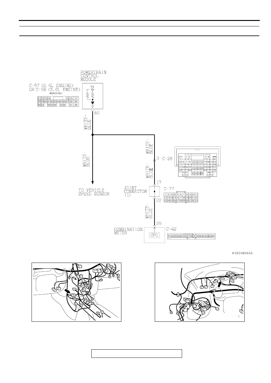
DTC 29: Vehicle Speed Sensor System
AC004689
Vehicle Speed Sensor System Circuit
AC
AC001741 AJ
CONNECTOR: C-28
AC001729AQ
CONNECTOR: C-42

AUTOMATIC TRANSAXLE DIAGNOSIS
TSB Revision
AUTOMATIC TRANSAXLE
23A-179
CIRCUIT OPERATION
•
4.8
−
5.2 volt voltage is applied to the vehicle
speed sensor output terminal (terminal 3) from
the PCM (terminal 80). The vehicle speed sensor
generates a pulse signal when the output
terminal is opened and ground.
•
The PCM compares the vehicle speed sensor
signal to input shaft and output shaft speed
sensor signals.
•
If the vehicle speed sensor becomes inoperative,
the transmission will not shift normally.
DTC SET CONDITIONS
If the PCM detects no pulse signal from the vehicle
speed sensor for continuous period of 30 seconds
under following conditions, it is judged as a vehicle
sensor system malfunction and DTC number "29" is
displayed.
•
Driving forward
•
Output shaft speed is 900 r/min or more
TROUBLESHOOTING HINTS (The most likely
causes for this code to be set:)
•
Malfunction of the vehicle speed sensor circuit
•
Damaged harness, connector
•
Malfunction of the PCM
DIAGNOSIS
Required Special Tool:
MB991502: Scan Tool (MUT-II)
STEP 1. Check the speedometer.
Q: Is the speedometer operating properly?
YES : Go to Step 2.
NO : Check the vehicle speed sensor. Refer to GROUP
54A, On-vehicle Service
−
Combination Meters
Assembly and Vehicle Speed Sensor
AC001657
CONNECTOR: C-57 <2.4L ENGINE> OR
C-59 <3.0L ENGINE>
AK
PCM
AC001729AR
CONNECTOR: C-77
Нет комментариевНе стесняйтесь поделиться с нами вашим ценным мнением.
Текст