Mitsubishi Eclipse / Eclipse Spyder (2000-2002). Service and repair manual — part 179
MULTIPORT FUEL INJECTION (MFI) DIAGNOSIS
TSB Revision
MULTIPORT FUEL INJECTION (MFI) <2.4L ENGINE>
13A-415
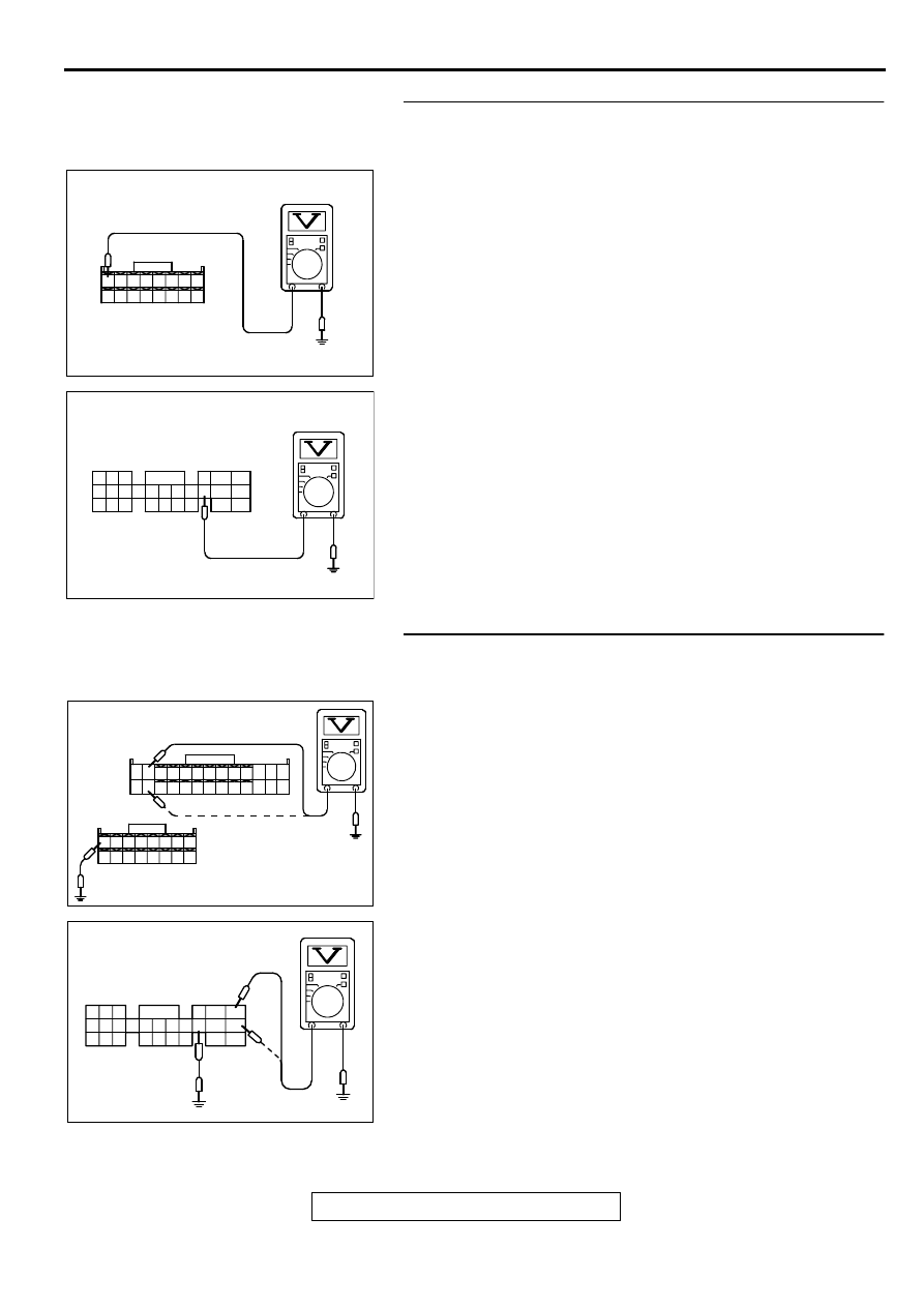
STEP 8. Check the power supply voltage at ECM harness
side connector C-53 <M/T> or PCM harness side connector
C-54 <A/T>.
(1) Disconnect the connector C-53 <M/T> or C-54 <A/T> and
measure at the harness side.
(2) Measure the voltage between terminal 38 <M/T> or 49 <A/
T> and ground.
•
Voltage should be battery positive voltage.
Q: Is the voltage normal?
YES : Go to Step 9.
NO : Repair harness wire between MFI relay connector A-
21X terminal 2 and ECM connector C-53 terminal 38
<M/T> or PCM connector C-54 terminal 49 <A/T>
because of open circuit. Then confirm that the
malfunction symptom is eliminated.
STEP 9. Check the power supply voltage at ECM harness
side connector C-49, C-53 <M/T> or PCM harness side
connector C-54 <A/T>.
(1) Disconnect the connector C-49,C-53 <M/T> or C-54 <A/T>
and measure at the harness side.
(2) Using a jumper wire, connect terminal 38 <M/T> or 49 <A/
T> to ground.
(3) Measure the voltage between terminal (12, 25) <M/T> or
(41, 47) <A/T> and ground.
•
Voltage should be battery positive voltage.
Q: Is the voltage normal?
YES : Replace the ECM or PCM. Then confirm that the
malfunction symptom is eliminated.
NO : Repair harness wire between MFI relay connector A-
21X terminal 1 and ECM connector C-49 terminal (12,
25) <M/T> or PCM connector C-54 terminal (41, 47)
<A/T> because of open circuit. Then confirm that the
malfunction symptom is eliminated.
AK000405
<M/T>
C-53 HARNESS
SIDE CONNECTOR
AC
31
32
33
34
35
36
37
38
39
40
41
42
43
44
45
46
AK000406AD
41
42
43
44
45
46
47
48
49
50
51
52
53
54
55
56
57
58
59
60
61
62
63
64
65
66
<A/T>
C-54 HARNESS
SIDE CONNECTOR
AK000407
1
2
3
4
5
6
7
8
9
10
11
12
13
14
15
16
17
18
19
20
21
22
23
24
25
26
31
32
33
34
35
36
37
38
39
40
41
42
43
44
45
46
<M/T>
HARNESS SIDE
CONNECTOR
C-49
C-53
AC
AKX01438
C-54 HARNESS
SIDE CONNECTOR
<A/T>
46 45 44
57 56 55
66 65 64
54 53 52 51 50 49 48 47
43 42 41
63 62 61 60
59 58
AG
MULTIPORT FUEL INJECTION (MFI) DIAGNOSIS
TSB Revision
MULTIPORT FUEL INJECTION (MFI) <2.4L ENGINE>
13A-416
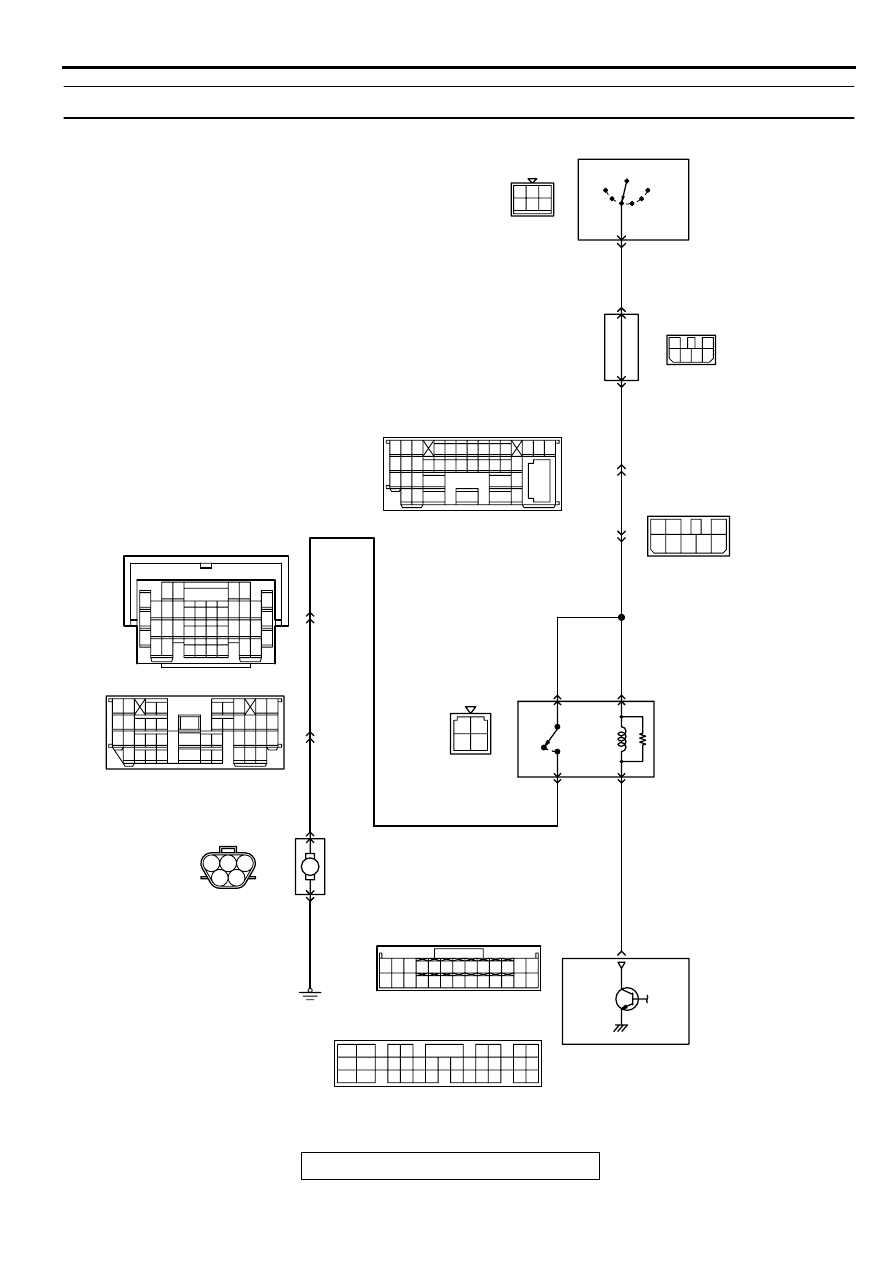
INSPECTION PROCEDURE 30: Fuel pump system.
AK000680
2
3 4
1 2 3
4
4
4 5 6
1 2
1
3
2
4 5
4
8
7
2
6
3
5
1
17
6
GREEN
3
BLA
CK-
WHITE
1
BLA
CK-
WHITE
BLA
CK-
WHITE
BLA
CK
WHITE
BLA
CK-
WHITE
1
12 13 14
18
30
41
34
3
16
10
6 7
19
31
42
20
32
43
21
33
25
24
26
36
35
37
29
28
15
27
38
8 9
39 40
11
2
22
5
23
5
BLA
CK
GREEN
GREEN
GREEN
BLA
CK
IG2
ST
LOCK
ACC
IG1
C-87
2
5
C-89
C-07
MU801333
29
JUNCTION
BLOCK
R
C-101
MU801331
IGNITION
SWITCH
3
ENGINE CONTROL
MODULE(ECM)<M/T>
OR
POWERTRAIN CONTROL
MODULE(PCM)<A/T>
FUEL PUMP AND
GAUGE UNIT
FUEL PUMP
RELAY
A-20X
3
4
1
2
22<M/T>
21<A/T>
6
C-90
C-28
D-17
(MU802058)
5
1
5
4
15 16
26 27 28 29
32 33 34
17 18 19 20 21 22 23 24 25
30 31
36 37
35
38
10
11 12 13
1 2 3
4 5 6 7 8 9
14
2
3 4
5 6
7 8
9
11 12 13 14 15 16 17 18 19 20
30
21 22 23
24 25
26 27 28 29
3132 33
34 35
1
14
4
19
5
22
6
17
8
15
9
18
7
20
16
2
13
12
23 24 25 26
21
1
3
10
C-49<M/T>
(MU803773)
C-50<A/T>
(MU803784)
10 11
7 8
5
3 4
35
34
10 11 12
2122 23 24
13 14 15
25 26 27
16
28
17
18 19 20
29
30 31
32 33
36 37
38
9
1 2
6
M
MULTIPORT FUEL INJECTION (MFI) DIAGNOSIS
TSB Revision
MULTIPORT FUEL INJECTION (MFI) <2.4L ENGINE>
13A-417
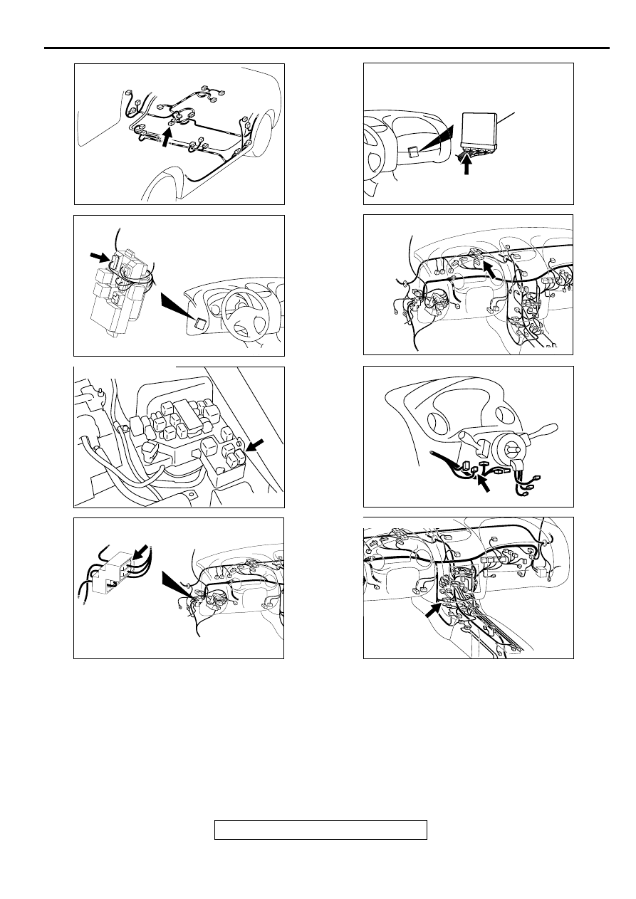
AK000734AC
CONNECTOR:D-17
AK000315
CONNECTOR:C-101
AC
AK000360AB
CONNECTOR : A-20X
AK000345AE
CONNECTOR:C-89
AK000280
C-49,C-50
ECM<M/T>
OR
PCM<A/T>
CONNECTORS:C-49<M/T>,C-50<A/T>
BC
AK000312AJ
CONNECTOR:C-07
AK000219
CONNECTOR:C-87
AC
AK000733AC
CONNECTOR:C-28
MULTIPORT FUEL INJECTION (MFI) DIAGNOSIS
TSB Revision
MULTIPORT FUEL INJECTION (MFI) <2.4L ENGINE>
13A-418
CIRCUIT OPERATION
•
A battery positive voltage is applied on the fuel
pump relay (terminal 3, 4) from the ignition
switch-IG.
•
During cranking and while the engine is running,
the ECM <M/T> or PCM <A/T> turns the power
transistor in the ECM <M/T> or PCM <A/T> ON
to ground the fuel pump relay coil. With this, the
fuel pump relay turns ON, and the battery positive
voltage is supplied to the fuel pump from the fuel
pump relay (terminal 1).
TROUBLESHOOTING HINTS (The most likely
causes for this code to be set are:)
))
)
•
Malfunction of the fuel pump relay.
•
Malfunction of the fuel pump.
•
Improper connector contact, open or short-
circuited harness wire.
•
Malfunction of the ECM <M/T> or PCM <A/T>.
DIAGNOSIS
Required Special Tool:
MB991502:Scan Tool (MUT-II)
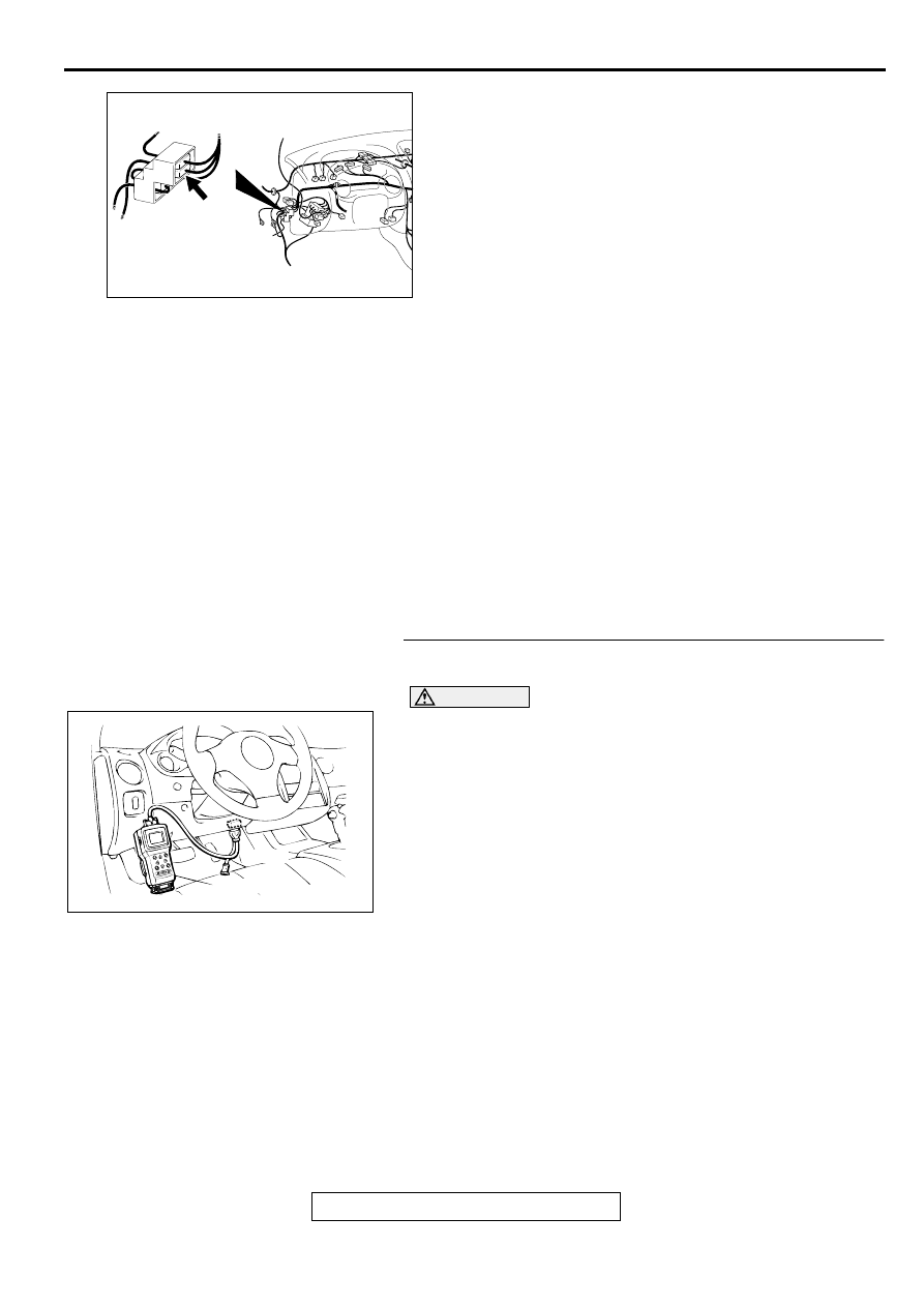
STEP 1. Using scan tool MB991502, check actuator test
item 07: Fuel Pump.
CAUTION
To prevent damage to scan tool MB991502, always turn the
ignition switch to the "LOCK" (OFF) position before
connecting or disconnecting scan tool MB991502.
(1) Connect scan tool MB991502 to the data link connector.
(2) Turn the ignition switch to the "ON" position.
(3) Set scan tool MB991502 to the actuator test mode for item
07, Fuel Pump.
•
An operation sound of the fuel pump should be heard.
(4) Turn the ignition switch to the "LOCK" (OFF) position.
Q: Is the fuel pump operating properly?
YES : That this malfunction is intermittent. Refer to GROUP
00, How to Use Troubleshooting/Inspection Service
Points (
).
NO : Go to Step 2.
AK000345
CONNECTOR:C-90
AD
AKX01177
16 PIN
MB991502
AB
Нет комментариевНе стесняйтесь поделиться с нами вашим ценным мнением.
Текст