Mitsubishi Eclipse / Eclipse Spyder (2000-2002). Service and repair manual — part 486
AUTOMATIC TRANSAXLE DIAGNOSIS
TSB Revision
AUTOMATIC TRANSAXLE
23A-236
DTC 54: A/T Contorl Relay System
AC004692AC
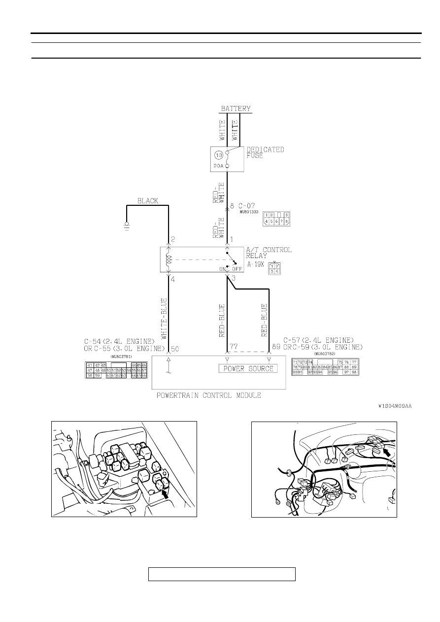
A/T Control Relay System Circuit
AC004306 AC
BATTERY
CONNECTOR: A-19X
AC001729 AM
CONNECTOR: C-07
AUTOMATIC TRANSAXLE DIAGNOSIS
TSB Revision
AUTOMATIC TRANSAXLE
23A-237
CIRCUIT OPERATION
•
A/T control relay (terminal number 1) receives the
battery positive voltage from the battery.
•
When turning the ignition switch to the "ON," the
PCM receives battery voltage from the ignition
switch (terminal 98). Then the PCM (terminal
number 50) applies a voltage to the A/T control
relay (terminal number 4), and the A/T control
relay switch is turned on. When the A/T control
relay switch is turned on, the battery applies a
power supply voltage to the PCM (terminal
numbers 77 and 89).
DTC SET CONDITIONS
If the A/T control relay voltage is less than 7 volts
after the ignition switch has been turned to the "ON,"
it is judged that there is an open circuit or a short-
circuit in the A/T control relay ground and diagnostic
trouble code number "54" is output. The transmission
is locked into the 3rd gear as a fail-safe measure,
and the "N" range light flashes once per second.
TROUBLESHOOTING HINTS (The most likely
causes for this code to be set:)
•
Malfunction of the A/T control relay
•
Damaged harness, connector
•
Malfunction of the PCM
DIAGNOSIS
Required Special Tool:
MB991502: Scan Tool (MUT-II)
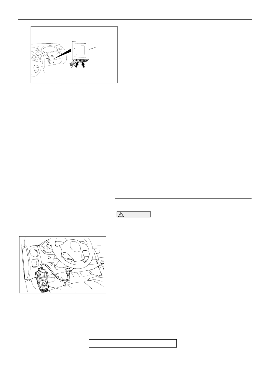
STEP 1. Using scan tool MB991502, check data list item 54:
A/T Control Relay Output Voltage.
CAUTION
To prevent damage to scan tool MB991502, always turn the
ignition switch to "LOCK" (OFF) position before
connecting or disconnecting scan tool MB991502.
(1) Connect scan tool MB991502 to the data link connector.
(2) Turn the ignition switch to "ON" position.
(3) Set scan tool MB991502 to data reading mode for item 54:
A/T Control Relay Output Voltage.
•
Voltage should be battery positive voltage.
(4) Turn the ignition switch to "LOCK" (OFF) position.
Q: Is the relay operating properly?
YES : This malfunction is intermittent. Refer to GROUP 00,
How to Use Troubleshooting/Inspection Service
Points
−
How to Cope with Intermittent Malfunction
NO : Go to Step 2.
AC001657
CONNECTORS: C-54 <2.4L ENGINE> OR
C-55 <3.0L ENGINE>, C-57 <2.4L ENGINE>
OR C-59 <3.0L ENGINE>
C-54 <2.4L ENGINE>
OR
C-55 <3.0L ENGINE>
C-57 <2.4L ENGINE>
OR
C-59 <3.0L ENGINE>
AJ
PCM
AC001252
MB991502
16 PIN
AB
AUTOMATIC TRANSAXLE DIAGNOSIS
TSB Revision
AUTOMATIC TRANSAXLE
23A-238
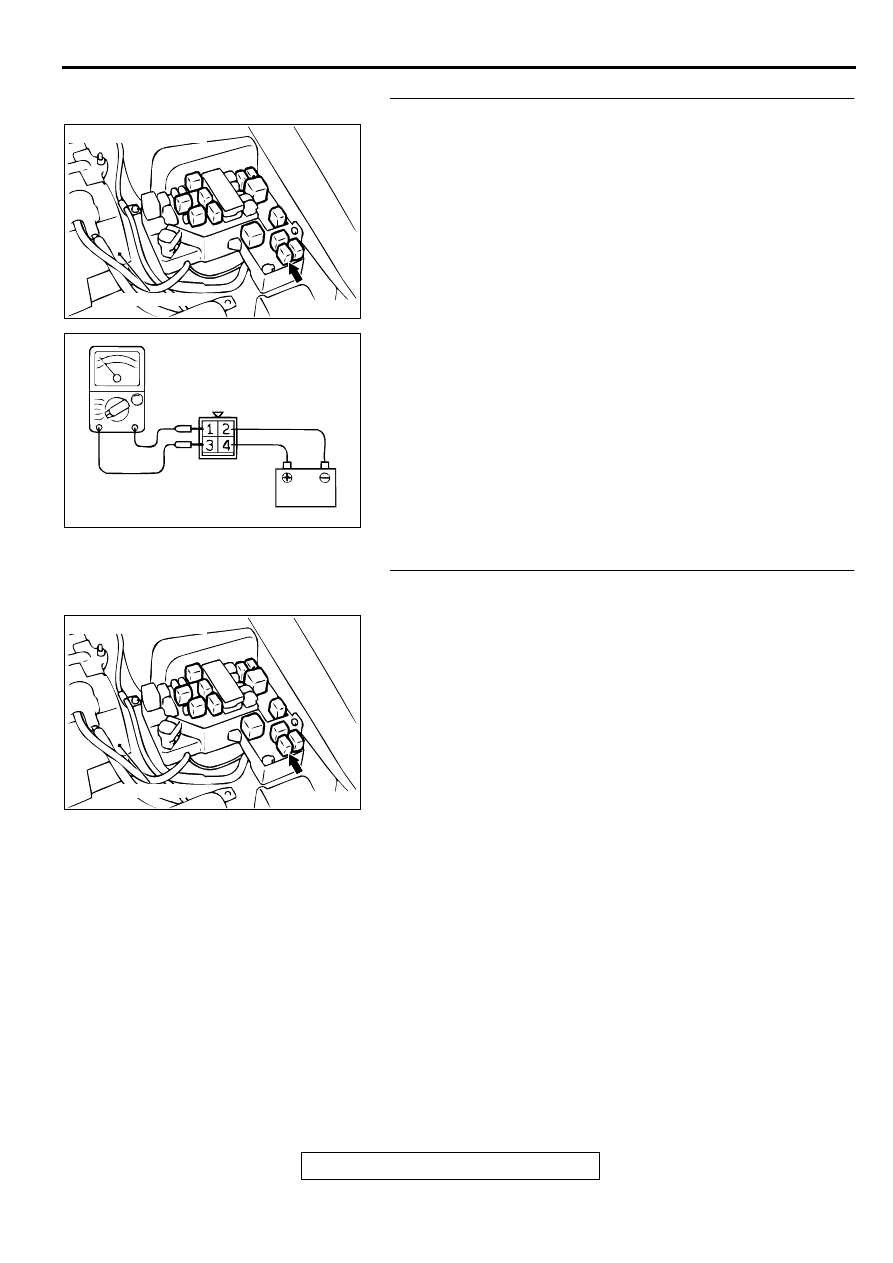
STEP 2. Check the A/T control relay.
(1) Remove the A/T control relay A-19X.
(2) Use jumper wires to terminal 2 of A/T control relay
connector A-19X to the negative battery terminal, and
terminal number 4 of A/T control relay connector A-19X to
the positive battery terminal.
(3) Measure the resistance between terminal 1 and 3 of A/T
control relay connector A-19X.
•
Should be than 2 ohm when the jumper wire connected.
•
Open circuit when the jumper wire disconnected.
Q: Is the resistance normal?
YES : Go to Step 3.
NO : Replace the A/T control relay.
STEP 3. Check connector A-19X at A/T control relay for
damage.
Q: Is the connector in good condition?
YES : Go to Step 4.
NO : Repair or replace it. Refer to GROUP 00E, Harness
Connector Inspection
.
AC004306 AC
BATTERY
CONNECTOR: A-19X
ACX01205
HARNESS
CONNECTOR: A-19X
AD
AC004306 AC
BATTERY
CONNECTOR: A-19X
AUTOMATIC TRANSAXLE DIAGNOSIS
TSB Revision
AUTOMATIC TRANSAXLE
23A-239
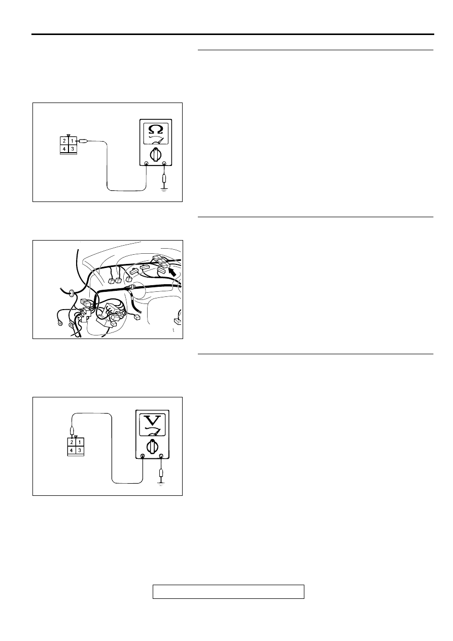
STEP 4. Check the power supply voltage at A/T control
relay connector A-19X.
(1) Disconnect the A/T control relay and measure at the
connector side.
(2) Turn the ignition switch to "ON" position.
(3) Measure the voltage between terminal 1 and ground.
•
Voltage should be battery positive voltage.
(4) Turn the ignition switch to "LOCK" (OFF) position.
Q: Is the voltage normal?
YES : Go to Step 6.
NO : Go to Step 5.
STEP 5. Check connector C-07 at intermediate connector
for damage.
Q: Is the connector in good condition?
YES : Repair it because of harness open circuit or short
circuit to ground between A/T control relay connector
A-19X terminal 1 and battery.
NO : Repair or replace it. Refer to GROUP 00E, Harness
Connector Inspection
.
STEP 6. Check the continuity at A/T control relay
connector A-19X.
(1) Disconnect the A/T control relay and measure at the
connector side.
(2) Check for the continuity between terminal 2 and ground.
•
Should be less than 2 ohm.
Q: Is the continuity normal?
YES : Go to Step 7.
NO : Repair it because of harness open circuit or damage
between A/T control relay connector A-19X terminal 2
and the earth.
ACX02168
HARNESS
CONNECTOR: A-19X
AC
AC001729 AM
CONNECTOR: C-07
ACX02172
HARNESS
CONNECTOR: A-19X
AC
Нет комментариевНе стесняйтесь поделиться с нами вашим ценным мнением.
Текст