Mitsubishi Eclipse / Eclipse Spyder (2000-2002). Service and repair manual — part 83
MULTIPORT FUEL INJECTION (MFI) DIAGNOSIS
TSB Revision
MULTIPORT FUEL INJECTION (MFI) <2.4L ENGINE>
13A-31
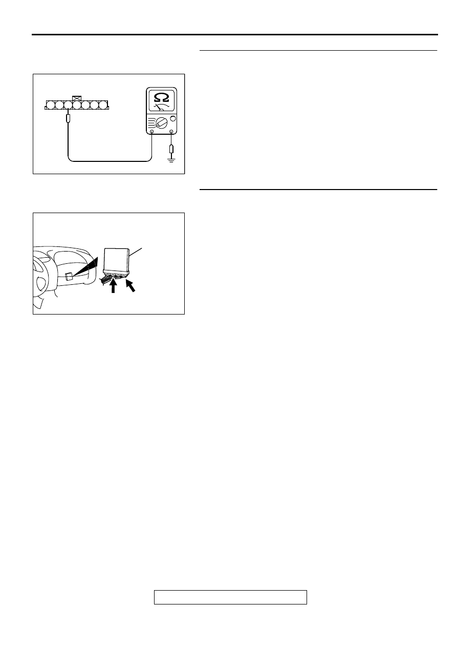
STEP 9. Check the continuity at volume air flow sensor
harness side connector B-14.
(1) Disconnect the connector B-14 and measure at the harness
side.
(2) Check for the continuity between terminal 5 and ground.
•
Should be less than 2 ohm.
Q: Is the continuity normal?
YES : Go to Step 12.
NO : Go to Step 10.
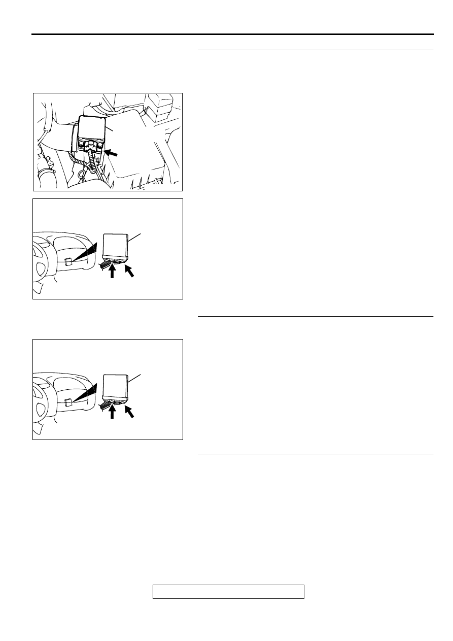
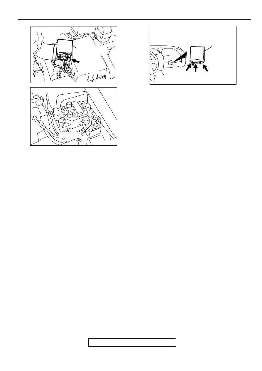
STEP 10. Check connector C-60 at ECM <M/T> or
connector C-54 at PCM <A/T> for damage.
Q: Is the connector in good condition?
YES : Go to Step 11.
NO : Repair or replace it. Refer to GROUP 00E, Harness
Connector Inspection (
). Then go to Step 13.
AKX01409AC
B-14 HARNESS
SIDE CONNECTOR
7 6 5 4 3 2 1
AK000280
C-54
C-60
ECM<M/T>
OR
PCM<A/T>
CONNECTORS:C-60<M/T>,C-54<A/T>
BB
MULTIPORT FUEL INJECTION (MFI) DIAGNOSIS
TSB Revision
MULTIPORT FUEL INJECTION (MFI) <2.4L ENGINE>
13A-32
STEP 11. Check for open circuit and harness damage
between volume air flow sensor connector B-14 terminal 5
and ECM connector C-60 terminal 92 <M/T> or PCM
connector C-54 terminal 57 <A/T>.
Q: Is the harness wire in good condition?
YES : Replace the ECM or PCM. Then go to Step 13.
NO : Repair it. Then go to Step 13.
STEP 12. Check connector C-60 at ECM <M/T> or
connector C-54 at PCM <A/T> for damage.
Q: Is the connector in good condition?
YES : Replace the volume air flow sensor. Then go to Step
13.
NO : Repair or replace it. Refer to GROUP 00E, Harness
Connector Inspection (
). Then go to Step 13.
STEP 13. Test the OBD-II drive cycle.
(1) Carry out a test drive with the drive cycle pattern. Refer to,
Procedure 6
−
Other Monitor (
).
(2) Check the diagnostic trouble code (DTC).
Q: Is the DTC P0101 is output?
YES : Retry the troubleshooting.
NO : The inspection is complete.
ACX02480
CONNECTOR : B-14
AC
VOLUME AIR
FLOW SENSOR
AK000280
C-54
C-60
ECM<M/T>
OR
PCM<A/T>
CONNECTORS:C-60<M/T>,C-54<A/T>
BB
AK000280
C-54
C-60
ECM<M/T>
OR
PCM<A/T>
CONNECTORS:C-60<M/T>,C-54<A/T>
BB
MULTIPORT FUEL INJECTION (MFI) DIAGNOSIS
TSB Revision
MULTIPORT FUEL INJECTION (MFI) <2.4L ENGINE>
13A-33
DTC P0102: Volume Air Flow Circuit Low Input
AK000652
1 2 3 4 5 6 7
42 43
48 49 50 51 52 53 54 55 56 57
46
45
44
58 59
60 61 62 63
64 65 66
2
3 4
5 6
7 8
9
11 12 13 14 15 16 17 18 19 20
30
21 22 23
24
25
26 27 28 29
31 32 33
34 35
1
14
RED
RED
-
WHITE
RED
-
WHITE
47
4
19
5
22
6
17
8
15
9
18
7
20
16
2
13
12
23 24 25 26
21
1
3
41
10
RED
-
WHITE
3 4
1 2
GREEN-BL
UE
BL
ACK
WHITE-GREEN
82
78
81
80
89 90 91 92
79
87
71
74
73
72
76
75
77
85
88
83 84
86
B-14
MFI
RELAY
BATTERY
VOLUME AIR
FLOW SENSOR
5V
19
7
92<M/T>*1
57<A/T>*2
90<M/T>*1
65<A/T>*2
4
5
3
C-60<M/T>
(MU803772)
C-49<M/T>
(MU803773)
C-50<A/T>
(MU803784)
C-54<A/T>
(MU803781)
NOTE
*1:ECM connector C-60<M/T>
*2:PCM connector C-54<A/T>
ENGINE CONTROL
MODULE(ECM)<M/T>
OR
POWERTRAIN CONTROL
MODULE(PCM)<A/T>
3
4
1
2
A-21X
10 11
MULTIPORT FUEL INJECTION (MFI) DIAGNOSIS
TSB Revision
MULTIPORT FUEL INJECTION (MFI) <2.4L ENGINE>
13A-34
CIRCUIT OPERATION
•
The volume air flow sensor power is supplied
from the MFI relay (terminal 1), and the ground is
provided on the ECM (terminal 92) <M/T> or
PCM (terminal 57) <A/T>.
•
5-volt power is applied to the volume air flow
sensor output terminal (terminal 3) from the ECM
(terminal 90) <M/T> or PCM (terminal 65) <A/T>.
The volume air flow sensor generates a pulse
signal when the output terminal and ground are
opened/closed (opened/short).
TECHNICAL DESCRIPTION
•
While the engine is running, the volume air flow
sensor outputs a pulse signal which corresponds
to the volume of air flow.
•
The ECM <M/T> or PCM <A/T> checks whether
the frequency of this signal output by the volume
air flow sensor while the engine is running is at or
above the set value.
DTC SET CONDITIONS
Check Conditions
•
Throttle position sensor voltage is 1.5 volts or
higher.
•
Engine speed is higher than 2,000 r/min.
Judgement Criteria
•
Volume air flow sensor output frequency has
continued to be 60 Hz or lower for 2 seconds.
TROUBLESHOOTING HINTS (The most likely
causes for this code to be set are:)
•
Volume air flow sensor failed.
•
Open or shorted volume air flow sensor circuit, or
loose connector.
•
ECM failed. <M/T>
•
PCM failed. <A/T>
•
Air leak between volume air flow sensor and
throttle body.
DIAGNOSIS
Required Special Tools
MB991502: Scan Tool (MUT-II)
ACX02480
CONNECTOR : B-14
AC
VOLUME AIR
FLOW SENSOR
AK000226
AK000226AB
CONNECTOR : A-21X
MFI RELAY
AK000280
C-49,
C-50
C-54
C-60
ECM<M/T>
OR
PCM<A/T>
CONNECTORS:C-49,C-60<M/T>,
C-50,C-54<A/T>
BA
Нет комментариевНе стесняйтесь поделиться с нами вашим ценным мнением.
Текст