Mitsubishi Eclipse / Eclipse Spyder (2000-2002). Service and repair manual — part 399
ON-VEHICLE SERVICE
TSB Revision
CLUTCH
21A-7
Step 4. Check the torsion spring for weak and
damage.
Q: Is the torsion spring worn or damaged?
YES :
Replace the clutch disc. Then go to Step 7.
NO :
Go to Step 5.
Step 5. Check the pressure plate and flywheel for
damage.
Q: Is the pressure plate or flywheel damaged?
YES :
Repair the clutch cover assembly or
flywheel. Then go to Step 7.
NO :
Go to Step 6.
Step 6. Check the mounting for loosening and
damage.
Q: Is the mounting loosened or damaged?
YES :
Tighten or replace the mounting. Then go to
Step 7.
NO :
Go to Step 7.
Step 7. Check the symptom.
Q: Is the symptom reproduced?
YES :
Return to Step 1.
NO :
This diagnosis is complete.
O N -VEH IC LE SERVIC E
CLUTCH PEDAL CHECK AND ADJUSTMENT
M1211000900047
1. Turn back the carpet etc. under the clutch pedal.
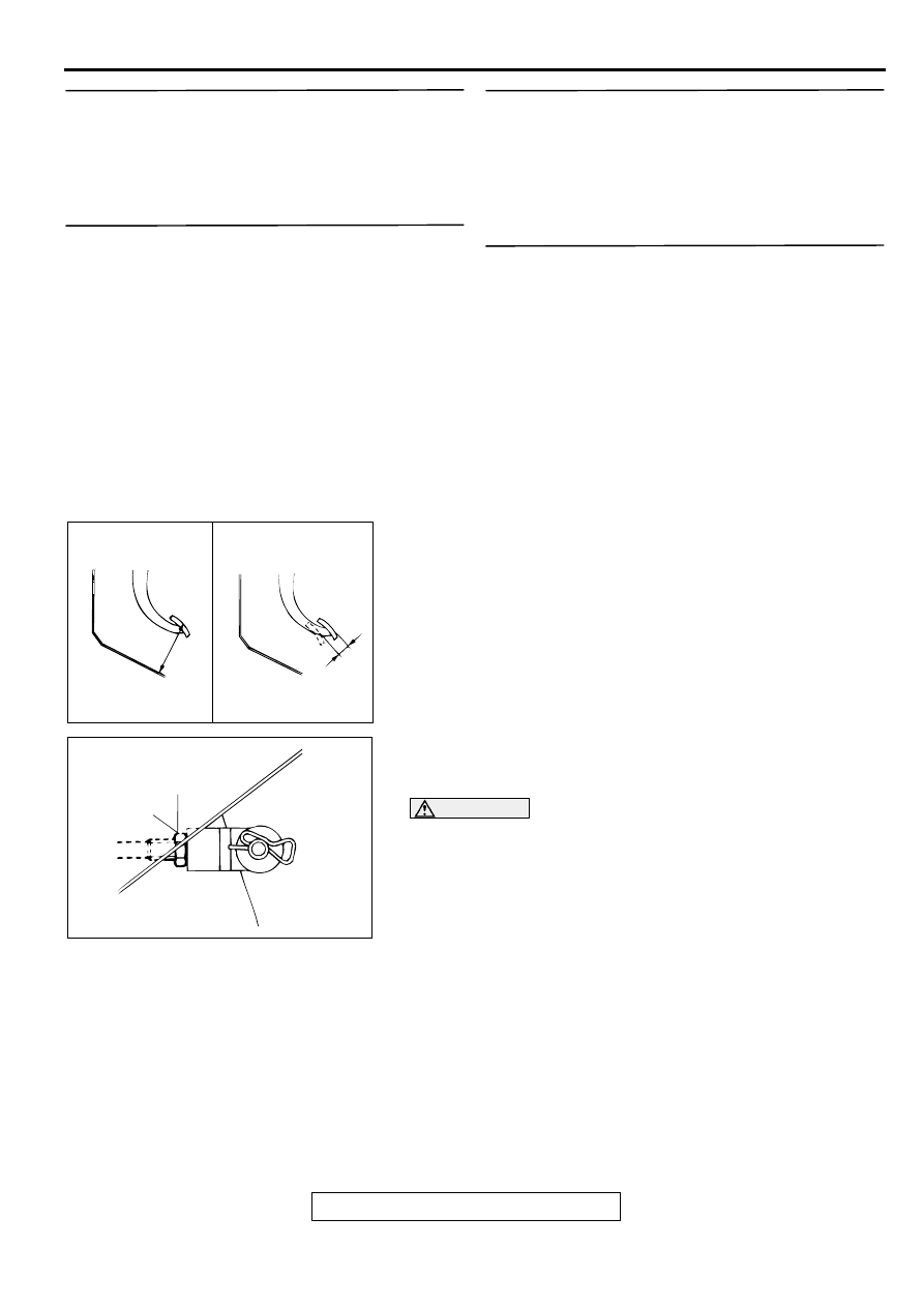
2. Measure the clutch pedal height and the clutch pedal clevis
pin play.
Standard value (A): 175.3
−
178.3 mm (6.90
−
7.02
inches) [From the surface of melting sheet (Floor
board shield) to the face of pedal pad]
Standard value (B): 1
−
3 mm (0.04
−
0.12 inch)
3. If the height of the clutch pedal is not within the standard
value, loosen the locking nut and adjust the pedal height to
the standard value using the adjusting bolt or push rod.
CAUTION
Do not push in the master cylinder push rod at this time.
4. If the clutch pedal play is not within the standard value,
loosen the locking nut and move the push rod to adjust.
AC001133
CLUTCH PEDAL
HEIGHT
CLUTCH PEDAL
CLEVIS PIN PLAY
A
B
AB
AC001134AB
LOCKING NUT
13 ± 2 N·m
111 ± 22 in-lb
ON-VEHICLE SERVICE
TSB Revision
CLUTCH
21A-8
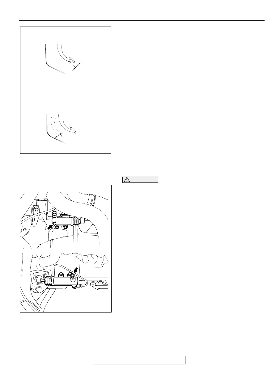
5. After the adjustments, confirm that the clutch pedal free play
(measured at the face of the pedal pad) and the distance
between the clutch pedal (the face of the pedal pad) and the
floorboard when the clutch is disengaged are within the
standard value ranges.
Standard value (C): 6
−
13 mm (0.2
−
0.5 inch)
Standard value (D): 76.4 mm (3.0 inches) or more
6. If the measured free play and distance do not agree with the
standard value ranges, it is probably the result of either air in
the hydraulic system or a faulty master cylinder or clutch.
Bleed the air, or disassemble and inspect the master
cylinder or clutch.
7. Reinstall the carpet, etc.
CLUTCH BLEEDING
M1211001400045
CAUTION
Use the specified brake fluid. Avoid using a mixture of the
specified fluid and other fluid.
Specified fluid: Brake Fluid DOT 3 or DOT 4
CLUTCH PEDAL POSITION SWITCH CHECK
M1211003100040
Refer to GROUP 17, Auto-cruise Control System
−
On-vehicle
Service
−
Auto-cruise Control Component Check
AC001135
CLUTCH PEDAL FREE PLAY
DISTANCE BETWEEN THE CLUTCH PEDAL
AND THE FLOORBOARD WHEN THE
CLUTCH IS DISENGAGED
C
D
AB
AC001136AB
<3.0L ENGINE>
<2.4L ENGINE>
ON-VEHICLE SERVICE
TSB Revision
CLUTCH
21A-9
CLUTCH INTERLOCK SWITCH OPERATING
CHECK
M1211001000047
1. Lock the front wheels, apply the parking brake.
2. After normally adjusting the clutch pedal, check the interlock
switch operation as follows:
(1) The engine should not start even if the ignition switch is
turned to the "START" position with the clutch pedal not
depressed. If the engine should start, check the interlock
switch and the harness.
(2) The engine should start after the clutch has been
disengaged while the clutch pedal is depressed with the
ignition switch turned to the "START" position. If the
engine should start before the clutch pedal is disengaged
or the engine does not start even if the clutch pedal is
depressed, adjust the interlock switch.
CLUTCH INTERLOCK SWITCH CHECK AND
ADJUSTMENT
M1211001100044
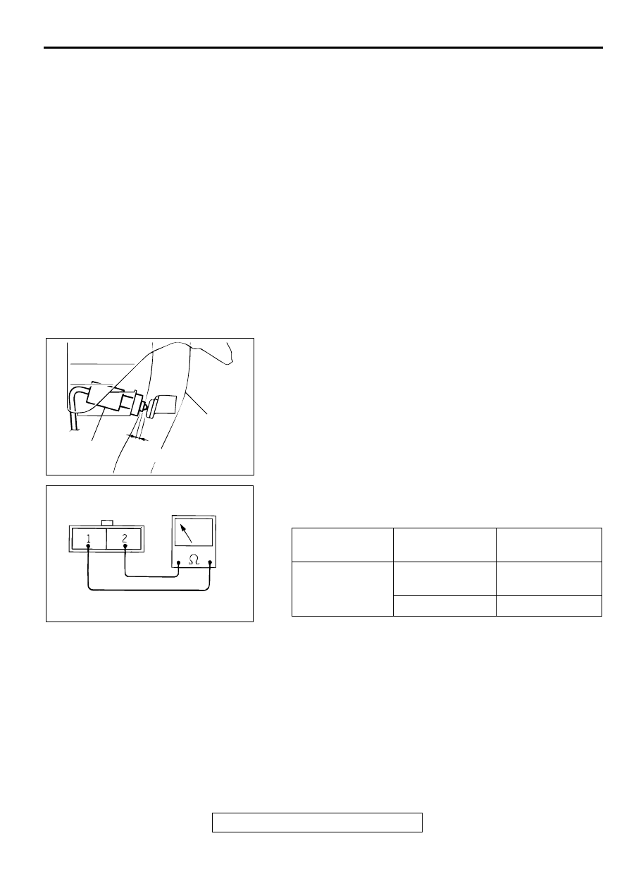
1. Check to be sure that the interlock switch is as shown in the
illustration when the clutch pedal is depressed at its full
stroke 130 mm (5.1 inches). If the specified dimension is not
met, loosen the clutch interlock switch 1/4 turns
counterclockwise. Then slide the switch to the specified
dimension, and turn the switch 1/4 turns clockwise to lock.
2. Connect an ohmmeter to the interlock switch connector, and
then check for continuity when the clutch pedal is fully
depressed and when it is released outward.
TESTER
CONNECTION
PEDAL
POSITION
SPECIFIED
CONDITION
1
−
2
FULLY
DEPRESSED
No Continuity
RELEASED
Continuity
AC001137AB
CLUTCH PEDAL
3.5 mm
(0.14 in)
CLUTCH
INTERLOCK
SWITCH
AC001138
CLUTCH PEDAL
TSB Revision
CLUTCH
21A-10
C LU TC H PED A L
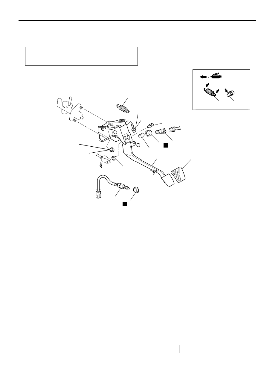
REMOVAL AND INSTALLATION
M1211001600049
INSPECTION
M1211001700046
•
Check the bushing for wear.
•
Check the clutch pedal for bending or twisting.
•
Check the return spring for damage or deterioration.
•
Check the turnover spring for damage or deterioration.
•
Check the pedal pad for damage or wear.
Post-installation Operation
•
Clutch Pedal Adjustment (Refer to
•
Clutch Interlock Switch Adjustment (Refer to
AC001615
5
1
6
5
12 ± 2 N·m
102 ± 22 in-lb
4
1
11
9
12
10
N
7
N
N
8
2
3
13 ± 2 N·m
111 ± 22 in-lb
AC
REMOVAL STEPS
1.
CLEVIS PIN
2.
BUSHING
3.
NUT
4.
BOLT
5.
RETURN SPRING
6.
CLUTCH INTERLOCK SWITCH
7.
CLIP
8.
CLUTCH PEDAL POSITION
SWITCH
9.
CLIP
10. PEDAL STOPPER
11. CLUTCH PEDAL AND PEDAL
SUPPORT MEMBER
12. PEDAL PAD
REMOVAL STEPS (Continued)
Нет комментариевНе стесняйтесь поделиться с нами вашим ценным мнением.
Текст