Mitsubishi Eclipse / Eclipse Spyder (2000-2002). Service and repair manual — part 630
DOOR
TSB Revision
BODY
42-67
CAUTION
Ensure that the weatherstrip is not wrinkled or out of
position.
15.Install the drip line weatherstrip to the weatherstrip holder.
<ECLIPSE> (Refer to
.)
16.Install the topstack rail weatherstrip to the weatherstrip
holder. <ECLIPSE SPYDER> (Refer to
17.Install the door trim and the waterproof film (Refer to
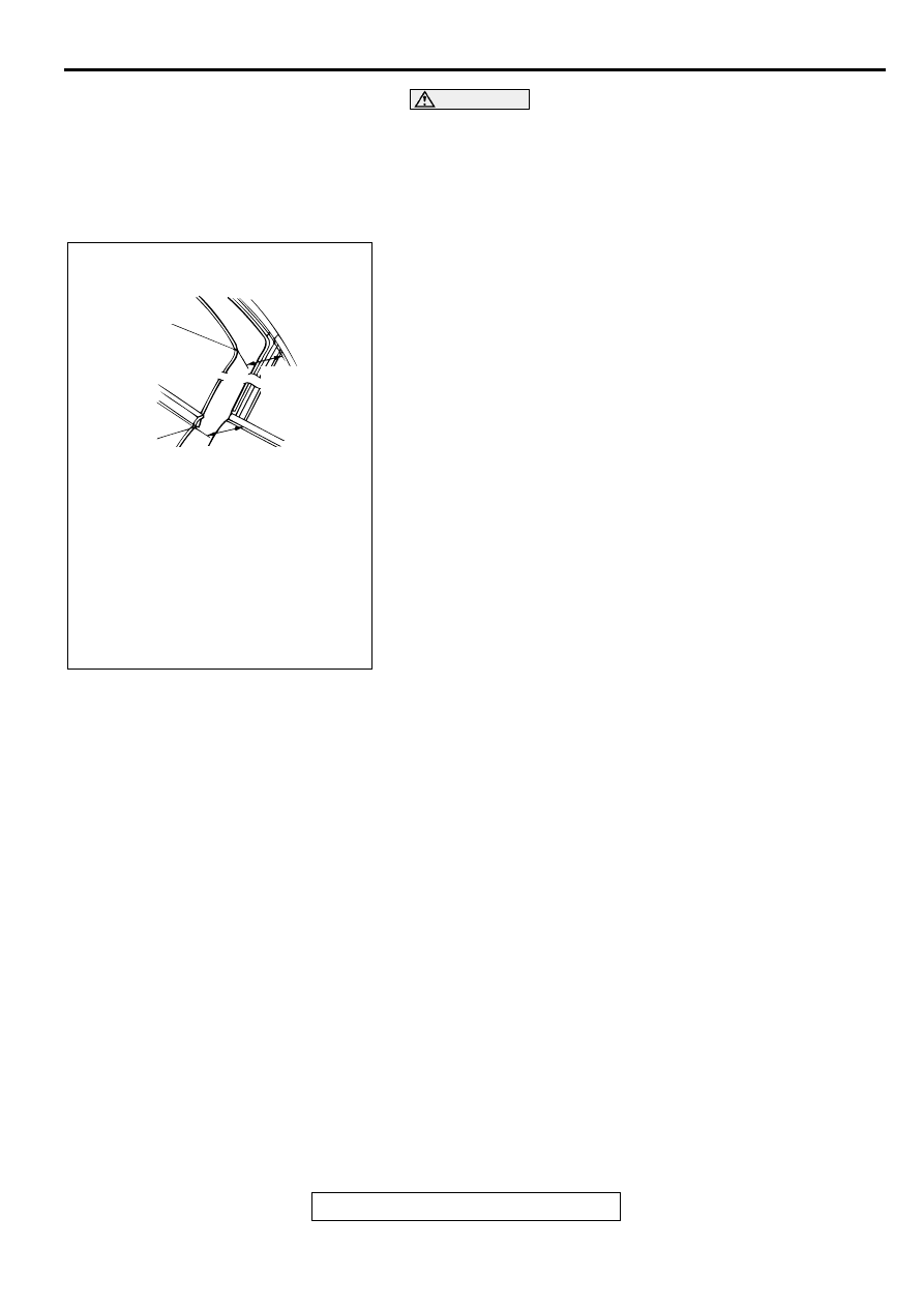
18.Check the door window glass alignment according to
following procedure.
(1) Close the door window glass fully, and close the door
until the clearance between the door window glass rear
end and the weatherstrip reaches 100 mm (3.9 inches).
At this time, the distance between the rear end of the belt
line molding outer and the quarter panel should be 113.5
−
118.5 mm (4.46
−
4.67 inches) <ECLIPSE> and 126
−
130 mm (4.9
−
5.1 inches) <ECLIPSE SPYDER>.
AC004087
DOOR GLASS
REAR END
100 mm
(3.9 in)
BELTLINE
MOULDING
OUTER
REAR END 113.5 – 118.5 mm (4.46 – 4.67 in)
<ECLIPSE>
126 – 130 mm (4.9 – 5.1 in)
<ECLIPSE SPYDER>
AB
DOOR
TSB Revision
BODY
42-68
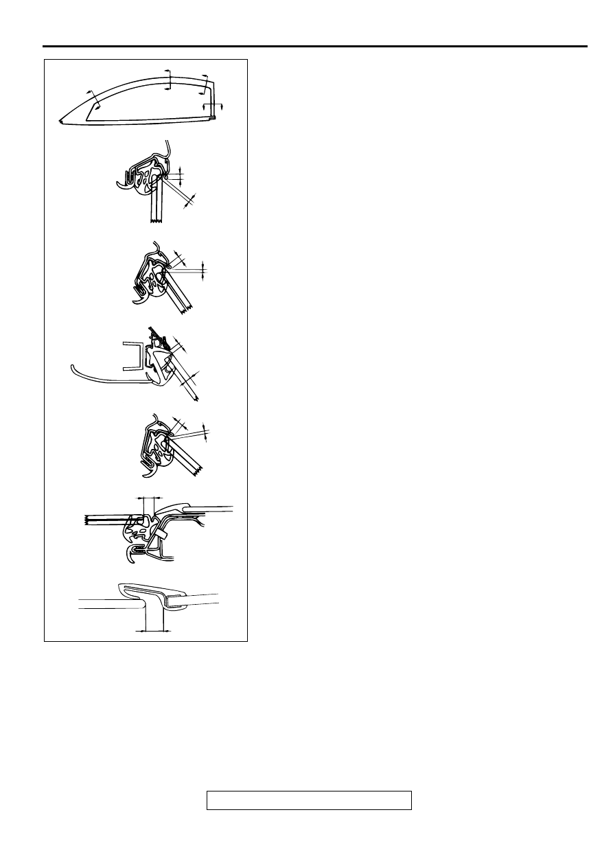
(2) The clearance between the glass and the glass catch
should be within the range of standard values (a, c, e, g)
when the window is fully closed and the door is closed
gently.
Standard value
(a): 2.9
±
1.0 mm (0.11
±
0.04 inches)
(c): 4.5
±
1.0 mm (0.18
±
0.04 inches)
(e): 5.0 mm (0.20 inches)
(g): 3.4 mm (0.13 inches)
(i): 10.7
±
1.0 mm (0.42
±
0.04 inches)
(j): 8.7 mm (0.32 inches)
NOTE: IF the clearance is too small, the glass catch will
move above the glass when the door is closed. If the
clearance is too large, wind noise may be generated at
high vehicle speeds because the glass catch is not
hooked onto the glass.
(3) The amount of catch of the door catch on the door glass
and the weatherstrip should be at the standard values b,
d, f:
when the window is closed fully and then the door is
closed.
Standard value
(b): 2.7
±
1.0 mm (0.11
±
0.04 inches)
(d): 2.7
±
1.0 mm (0.11
±
0.04 inches)
(f): 8.0 mm (0.32 inches)
(h): 2.4
±
1.0 mm (0.09
±
0.04 inches)
(4) The door glass should slide smoothly over its full range of
movement when the door is closed.
(5) The glass catch and the weatherstrip should be parallel
with the door glass and the two up-stops should touch
simultaneously when the glass is fully closed.
AC003393
M
M
N
N
O
O
P
P
SECTION M – M
<ECLIPSE>
SECTION N – N
<ECLIPSE>
<ECLIPSE SPYDER>
SECTION O – O
<ECLIPSE>
SECTION P – P
<ECLIPSE>
<ECLIPSE SPYDER>
a
b
c
d
e
f
g
h
i
j
AB
DOOR
TSB Revision
BODY
42-69
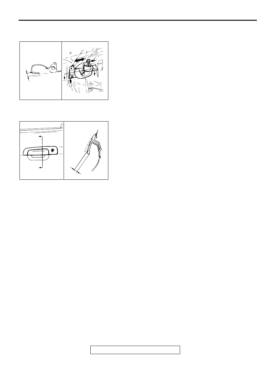
DOOR INSIDE HANDLE PLAY CHECK AND
ADJUSTMENT
M1423001500054
1. Check that the door inside handle play is within the standard
value range.
Standard value (A): 3.2 mm (0.13 inch)
2. If the door inside handle play is outside the standard value
range, remove the door trim. (Refer to
3. Loosen the inside handle mounting screws, and then move
the inside handle back and forth to adjust the play.
DOOR OUTSIDE HANDLE PLAY CHECK
M1423001600051
1. Check that the door outside handle play is within the
standard value range.
Standard value (B): 2.4 mm (0.09 inch)
2. If the door outside handle play is not within the standard
value range, check the door outside handle or the door latch
assembly. Replace if necessary.
CIRCUIT BREAKER (INCORPORATED IN THE
POWER WINDOW MOTOR) INSPECTION
M1429001000046
1. Pull the power window switch to the UP position to fully
close the door window glass, and keep pulling the switch for
a further 10 seconds.
2. Release the power window switch from the UP position and
immediately press it to the DOWN position. The condition of
the circuit breaker is good if the door window glass starts to
move downwards within 60 seconds.
AC000478
A
A
A
SECTION A – A
AB
AC000479
A
A
B
SECTION A – A
AB
DOOR
TSB Revision
BODY
42-70
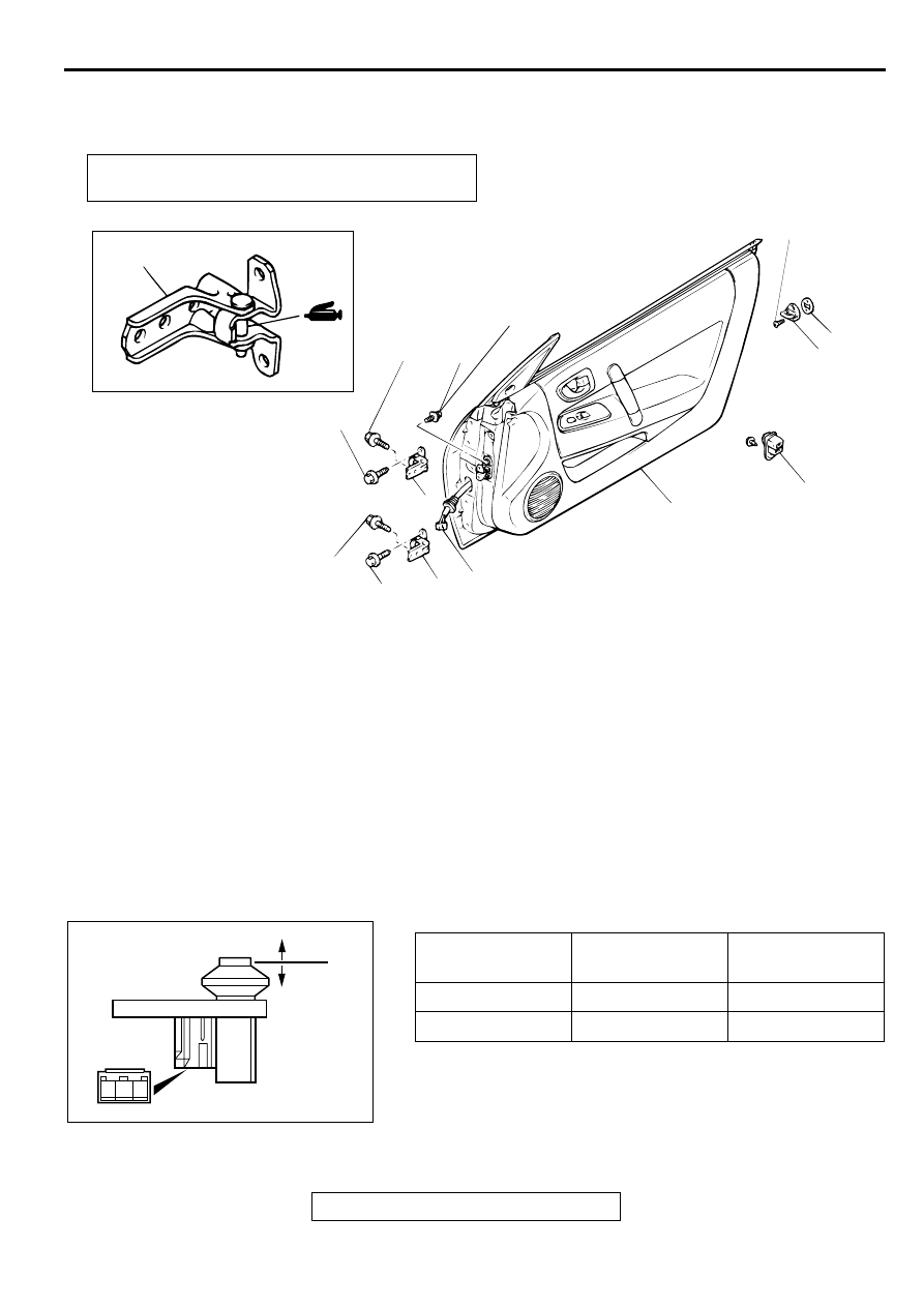
DOOR ASSEMBLY
REMOVAL AND INSTALLATION
M1423002200067
Required Special Tool
•
MB990900 or MB991164: Door Adjusting Wrench
INSPECTION
M1423006000076
DOOR SWITCH CONTINUITY CHECK
Post-installation Operation
•
AC000480
7, 8
5
7
4
8
6
1
2
3
26 ± 4 N·m
20 ± 4 ft-lb
21 ± 4 N·m
16 ± 2 ft-lb
26 ± 4 N·m
20 ± 4 ft-lb
21 ± 4 N·m
16 ± 2 ft-lb
5.0 ± 1.0 N·m
44 ± 9 in-lb
20 ± 4 N·m
15 ± 3 ft-lb
AB
DOOR SWITCH REMOVAL STEPS
1. DOOR SWITCH
STRIKER REMOVAL STEPS
2. STRIKER
3. STRIKER SHIM
DOOR ASSEMBLY REMOVAL STEPS
•
SCUFF PLATE AND COWL SIDE
TRIM (REFER TO GROUP 52A
4. HARNESS CONNECTOR
5. DOOR CHECK CONNECTING BOLT
6. DOOR ASSEMBLY
7. DOOR UPPER HINGE
8. DOOR LOWER HINGE
DOOR ASSEMBLY REMOVAL STEPS
SWITCH
POSITION
TESTER
CONNECTION
SPECIFIED
CONDITION
Released (ON)
1
−
2
Continuity
Depressed (OFF)
-
No Continuity
1 2 3
ACX01865AB
ON
OFF
Нет комментариевНе стесняйтесь поделиться с нами вашим ценным мнением.
Текст