Mitsubishi Eclipse / Eclipse Spyder (2000-2002). Service and repair manual — part 232
MULTIPORT FUEL INJECTION (MFI) DIAGNOSIS
TSB Revision
MULTIPORT FUEL INJECTION (MFI) <3.0L ENGINE>
13B-127
DTC P0135: O
2
Sensor Heater Circuit Malfunction (bank 1 sensor 1)
AK000691
3 4
1 2
3 4
1 2
RED
-
WHITE
RED
-
WHITE
RED
-
WHITE
RED
BL
UE-
WHITE
BATTERY
A-21X
3
4
1
2
RIGHT BANK HEATED
OXYGEN SENSOR(FRONT)
B-27
MU802605
1
2
3
4
TO ECM
OR PCM
TO ECM
OR PCM
ENGINE CONTROL
MODULE(ECM)<M/T>
OR
POWERTRAIN CONTROL
MODULE(PCM)<A/T>
4
MFI
RELAY
C-51<M/T>,C-52<A/T>
(MU803784)
2
3 4
5 6
7 8
9
11 12 13 14 15 16 17 18 19 20
30
21 22 23
24 25
26 27 28 29
3132 33
34 35
1
10
ACX02481
CONNECTOR : B-27
RIGHT BANK
HEATED OXYGEN
SENSOR(FRONT)
AC
AK000226
AK000226AB
CONNECTOR : A-21X
MFI RELAY
MULTIPORT FUEL INJECTION (MFI) DIAGNOSIS
TSB Revision
MULTIPORT FUEL INJECTION (MFI) <3.0L ENGINE>
13B-128
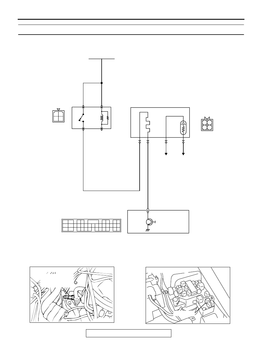
CIRCUIT OPERATION
•
Power is supplied from the MFI relay (terminal 1)
to the right bank heated oxygen sensor (front)
heater.
•
The ECM (terminal 4) <M/T> or PCM (terminal 4)
<A/T> controls continuity to the right bank heated
oxygen sensor (front) heater by turning the power
transistor in the ECM <M/T> or PCM <A/T> "ON"
and "OFF."
TECHNICAL DESCRIPTION
•
The ECM <M/T> or PCM <A/T> checks whether
the heater current is within a specified range
when the heater is energized.
DTC SET CONDITIONS
Check Conditions
•
Engine coolant temperature is higher than 20
°
C
(68
°
F).
•
While the right bank heated oxygen sensor (front)
heater is on.
•
Battery positive voltage is at between 11 and 16
volts.
Judgment Criteria
•
Heater current of the right bank heated oxygen
sensor (front) heater has continued to be lower
than 0.2 ampere or higher than 3.5 ampere for 6
seconds.
•
One monitor during one drive cycle
TROUBLESHOOTING HINTS (The most likely
causes for this code to be set are:)
•
Open or shorted right bank heated oxygen
sensor (front) heater circuit.
•
Open circuit in right bank heated oxygen sensor
(front) heater.
•
ECM failed. <M/T>
•
PCM failed. <A/T>
DIAGNOSIS
Required Special Tools
MD998464: Test Harness
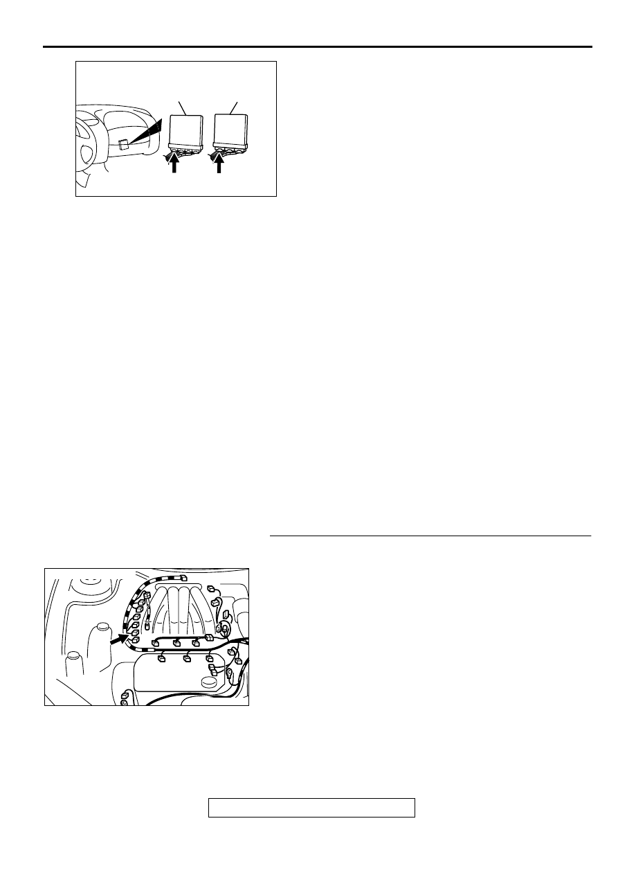
STEP 1. Check connector B-27at the right bank heated
oxygen sensor (front) for damage.
Q: Is the connector in good condition?
YES : Go to Step 2.
NO : Repair or replace it. Refer to GROUP 00E, Harness
Connector Inspection (
). Then go to Step 12.
AK000225
CONNECTOR : C-51<M/T>, C-52<A/T>
C-52
C-51
PCM<A/T>
ECM<M/T>
AJ
AK000208 AB
CONNECTOR : B-27
MULTIPORT FUEL INJECTION (MFI) DIAGNOSIS
TSB Revision
MULTIPORT FUEL INJECTION (MFI) <3.0L ENGINE>
13B-129
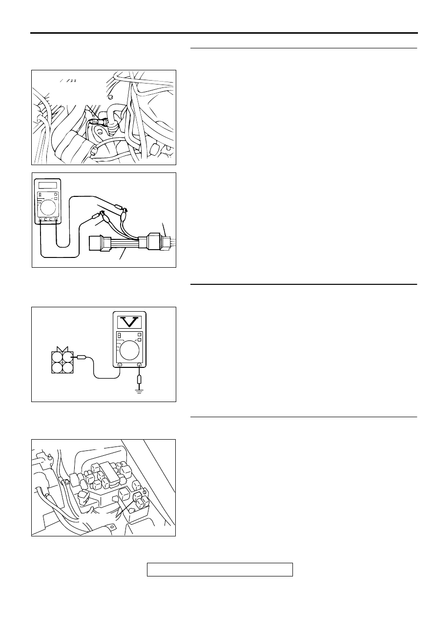
STEP 2. Check the right bank heated oxygen sensor
(front).
(1) Disconnect right bank heated oxygen sensor (front)
connector B-27 and connect test harness special tool,
MD998464, to the connector on the right bank heated
oxygen (front) sensor side.
(2) Measure the resistance between heated oxygen sensor
connector terminal 1 (red clip) and terminal 3 (blue clip).
Standard value: 4.5
−
8.0 ohm [at 20
°
C (68
°
F)]
Q: Is the resistance normal?
YES : Go to Step 3.
NO : Replace the right bank heated oxygen sensor (front).
Then go to Step 12.
STEP 3. Check the power supply voltage at right bank
heated oxygen sensor (front) harness side connector B-27.
(1) Disconnect the connector B-27 and measure at the harness
side.
(2) Turn the ignition switch to the "ON" position.
(3) Measure the voltage between terminal 1 and ground.
•
Voltage should be battery positive voltage.
(4) Turn the ignition switch to the "LOCK" (OFF) position.
Q: Is the voltage normal?
YES : Go to Step 5.
NO : Go to Step 4.
STEP 4. Check connector A-21X at the MFI relay for
damage.
Q: Is the connector in good condition?
YES : Repair harness wire between MFI relay connector A-
21X terminal 1 and right bank heated oxygen sensor
(front) connector B-27 terminal 1 because of open
circuit or short circuit to ground Then go to Step 12.
NO : Repair or replace it. Refer to GROUP 00E, Harness
Connector Inspection (
). Then go to Step 12.
ACX02481
CONNECTOR : B-27
RIGHT BANK
HEATED OXYGEN
SENSOR(FRONT)
AC
AKX01624
HEATED
OXYGEN
SENSOR
EQUIPMENT
SIDE
CONNECTOR
MD998464
BLUE
RED
AC
AKX01498 AG
2
1
4
3
B-27 HARNESS
SIDE CONNECTOR
AK000226
AK000226AB
CONNECTOR : A-21X
MFI RELAY
MULTIPORT FUEL INJECTION (MFI) DIAGNOSIS
TSB Revision
MULTIPORT FUEL INJECTION (MFI) <3.0L ENGINE>
13B-130
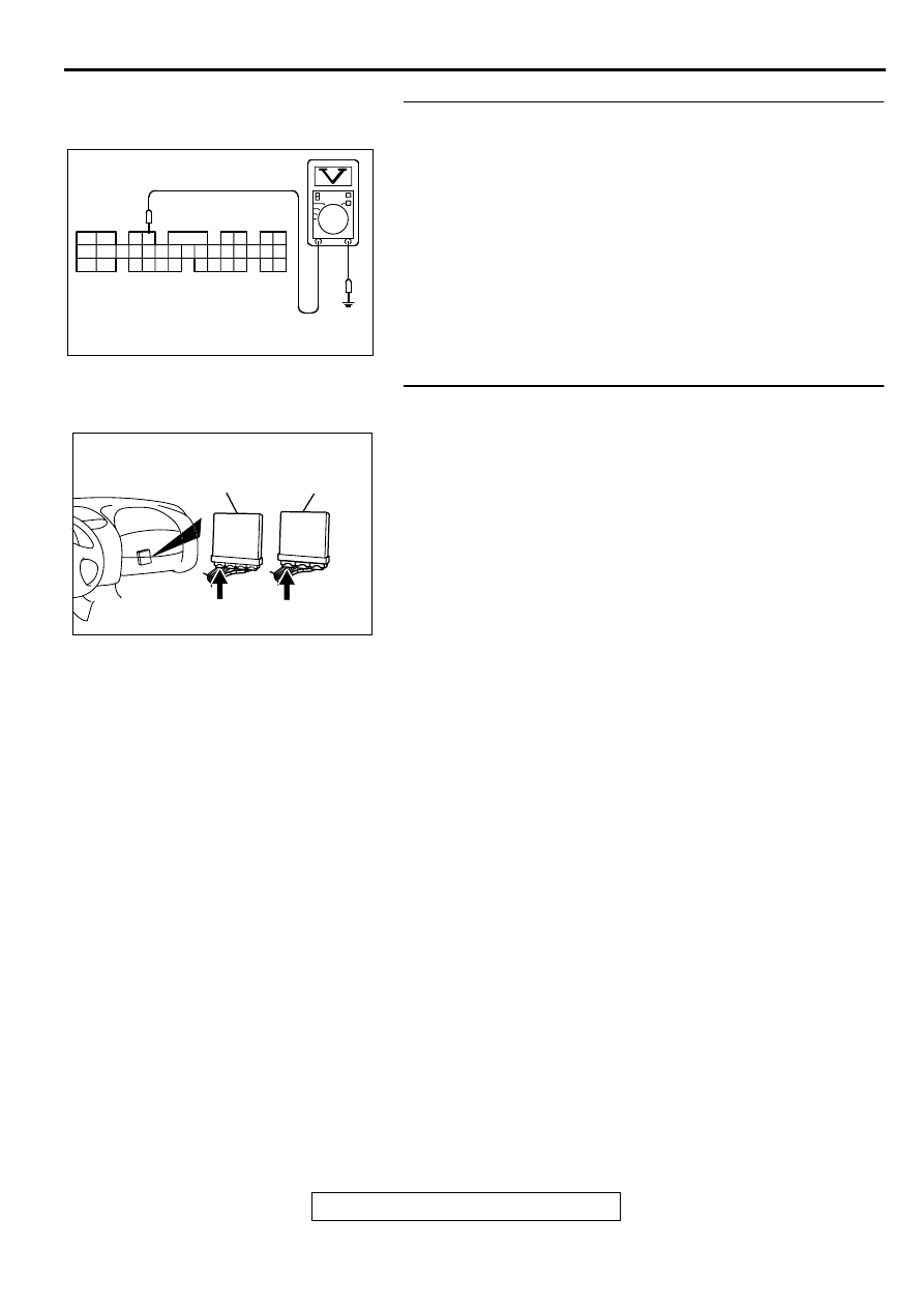
STEP 5. Check the power supply voltage at ECM connector
C-51 <M/T> or PCM connector C-52 <A/T> by backprobing.
(1) Do not disconnect the connector C-51 <M/T> or C-52 <A/
T>.
(2) Turn the ignition switch to the "ON" position.
(3) Measure the voltage between terminal 4 and ground by
backprobing.
•
Voltage should be battery positive voltage.
(4) Turn the ignition switch to the "LOCK" (OFF) position.
Q: Is the voltage normal?
YES : Go to Step 8.
NO : Go to Step 6.
STEP 6. Check connector C-51 at ECM <M/T> or connector
C-52 at PCM <A/T> for damage.
Q: Is the connector in good condition?
YES : Go to Step 7.
NO : Repair or replace it. Refer to GROUP 00E, Harness
Connector Inspection (
). Then go to Step 12.
AKX01534
1
2
3 4
5 6
7 8
9
10 11 12 13 14 15 16 17 18 19 20 21 22 23
24 25
26 27 28 29
30 31 32 33
34 35
C-51<M/T>, C-52<A/T>
CONNECTOR HARNESS
SIDE VIEW
AF
AK000225
CONNECTOR : C-51<M/T>, C-52<A/T>
C-52
C-51
PCM<A/T>
ECM<M/T>
AJ
Нет комментариевНе стесняйтесь поделиться с нами вашим ценным мнением.
Текст