Mitsubishi Eclipse / Eclipse Spyder (2000-2002). Service and repair manual — part 231
MULTIPORT FUEL INJECTION (MFI) DIAGNOSIS
TSB Revision
MULTIPORT FUEL INJECTION (MFI) <3.0L ENGINE>
13B-123
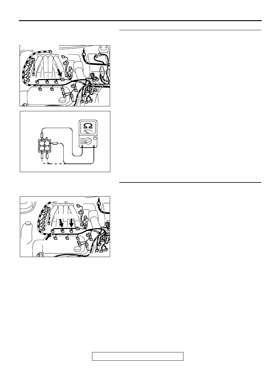
STEP 6. Check the right bank injector resistance at
intermediate connector B-48.
(1) Disconnect the injector intermediate connector B-48.
(2) Measure the resistance between each injector side
connector terminal.
a. Measure the resistance between terminal 1 and 2 when
measuring No.1 cylinder.
b. Measure the resistance between terminal 1 and 3 when
measuring No.3 cylinder.
c. Measure the resistance between terminal 1 and 4 when
measuring No.5 cylinder.
•
Resistance should be between 13 and 16 ohm [at 20
°
C(68
°
F)].
Q: Is the resistance normal?
YES : Go to Step 9.
NO : Go to Step 7.
STEP 7. Check connector B-01, B-05, B-26 at right bank
injector for damage.
(1) Remove the intake manifold.
(2) Check the right bank injector connector, which deviates
from the standard value at Step 6.
Q: Is the connector in good condition?
YES : Go to Step 8.
NO : Repair or replace it. Refer to GROUP 00E, Harness
Connector Inspection (
). Then go to Step 13.
AK000209AC
CONNECTOR:B-48
AK000240AB
INJECTOR
INTERMEDIATE
CONNECTOR
1 2
3 4
AK000210AB
B-05 B-26
B-01
CONNECTORS : B-01, B-05, B-26
MULTIPORT FUEL INJECTION (MFI) DIAGNOSIS
TSB Revision
MULTIPORT FUEL INJECTION (MFI) <3.0L ENGINE>
13B-124
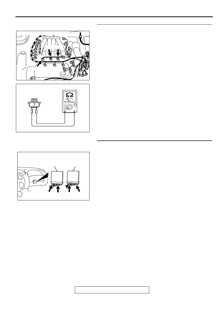
STEP 8. Check the right bank injector.
(1) Check the right bank injector connector, which deviates
from the standard value at Step 6.
(2) Measure the resistance between injector side connector
terminal 1 and 2.
Standard value: 13
−
16 ohm [at 20
°
C (68
°
F)]
Q: Is the resistance standard value?
YES : Repair harness wire between injector intermediate
connector and right bank injector connector because
of harness damage. Then go to Step 13.
NO : Replace the injector. Then go to Step 13.
STEP 9. Check connector C-51, C-62 at ECM <M/T> or
connector C-52, C-59 at PCM <A/T> for damage.
Q: Is the connector in good condition?
YES : Go to Step 10.
NO : Repair or replace it. Refer to GROUP 00E, Harness
Connector Inspection (
). Then go to Step 13.
AK000210AB
B-05 B-26
B-01
CONNECTORS : B-01, B-05, B-26
AK000559
2
1
INJECTOR SIDE
CONNECTOR
AB
AK000225
CONNECTORS : C-51, C-62<M/T>,
C-52, C-59<A/T>
C-52
C-51
PCM<A/T>
ECM<M/T>
AM
C-59
C-62
MULTIPORT FUEL INJECTION (MFI) DIAGNOSIS
TSB Revision
MULTIPORT FUEL INJECTION (MFI) <3.0L ENGINE>
13B-125
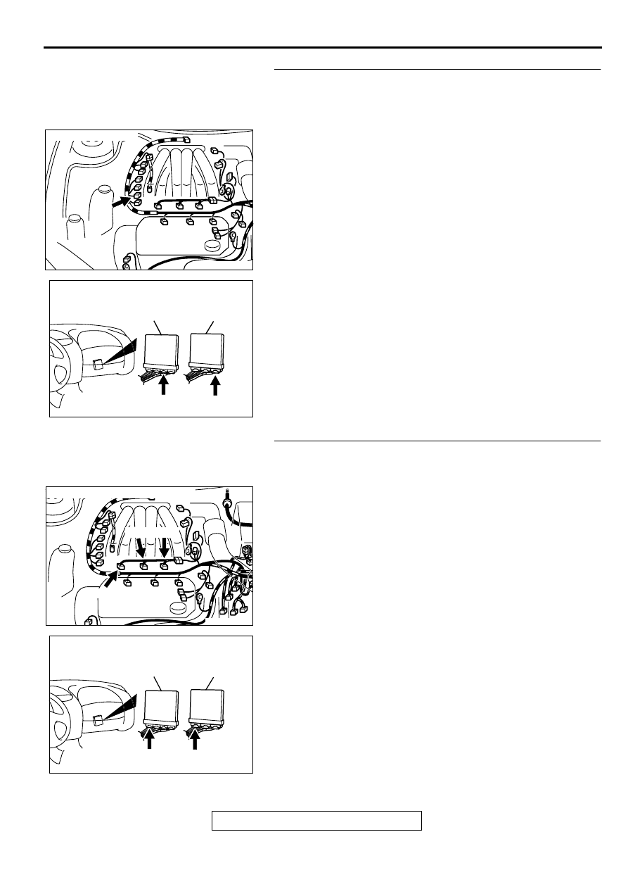
STEP 10. Check for harness damage between right bank
heated oxygen sensor (front) connector B-27 terminal 4
and ECM connector C-62 terminal 72 <M/T> or PCM
connector C-59 terminal 72 <A/T>.
Q: Is the harness wire in good condition?
YES : Go to Step 11.
NO : Repair it. Then go to Step 13.
STEP 11. Check for harness damage between right bank
injector connector and ECM connector <M/T> or PCM
connector <A/T>.
a. Check the harness wire between right bank injector
connector B-01 terminal 2 and ECM connector C-51
terminal 1 <M/T> or PCM connector C-52 terminal 1 <A/T>
when checking No.1 cylinder.
b. Check the harness wire between right bank injector
connector B-05 terminal 2 and ECM connector C-51
terminal 24 <M/T> or PCM connector C-52 terminal 24 <A/
T> when checking No.3 cylinder.
c. Check the harness wire between right bank injector
connector B-26 terminal 2 and ECM connector C-51
terminal 10 <M/T> or PCM connector C-52 terminal 10 <A/
T> when checking No.5 cylinder.
Q: Is the harness wire in good condition?
YES : Go to Step 12.
NO : Repair it. Then go to Step 13.
AK000208 AB
CONNECTOR : B-27
AK000225
CONNECTOR : C-62<M/T>, C-59<A/T>
C-59
C-62
PCM<A/T>
ECM<M/T>
AL
AK000210AB
B-05 B-26
B-01
CONNECTORS : B-01, B-05, B-26
AK000225
CONNECTOR : C-51<M/T>, C-52<A/T>
C-52
C-51
PCM<A/T>
ECM<M/T>
AJ
MULTIPORT FUEL INJECTION (MFI) DIAGNOSIS
TSB Revision
MULTIPORT FUEL INJECTION (MFI) <3.0L ENGINE>
13B-126
STEP 12. Check the fuel pressure.
Refer to
, Fuel Pressure Test.
Q: Is the fuel pressure normal?
YES : Replace the ECM or PCM. Then go to Step 13.
NO : Repair it. Then go to Step 13.
STEP 13. Test the OBD-II drive cycle.
(1) Carry out a test drive with the drive cycle pattern. Refer to
, Procedure 6
−
Other Monitor.
(2) Check the diagnostic trouble code (DTC).
Q: Is the DTC P0134 is output?
YES : Retry the troubleshooting.
NO : The inspection is complete.
Нет комментариевНе стесняйтесь поделиться с нами вашим ценным мнением.
Текст