Mitsubishi Eclipse / Eclipse Spyder (2000-2002). Service and repair manual — part 305
MULTIPORT FUEL INJECTION (MFI) DIAGNOSIS
TSB Revision
MULTIPORT FUEL INJECTION (MFI) <3.0L ENGINE>
13B-419
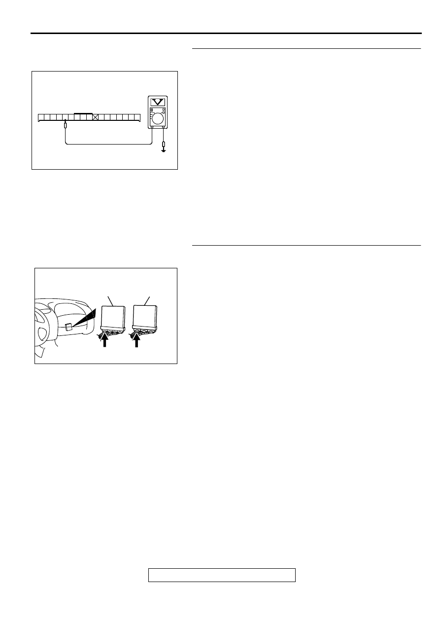
STEP 4. Check the power supply voltage at combination
meter harness side connector C-41.
(1) Disconnect the connector C-41 and measure at the harness
side.
(2) Turn the ignition switch to the "ON" position.
(3) Measure the voltage between terminal 52 and ground.
•
Voltage should be battery positive voltage.
(4) Turn the ignition switch to the "LOCK" (OFF) position.
Q: Is the voltage normal?
YES : Go to Step 5.
NO : Check harness connectors C-104 and C-101 at
intermediate connector for damage, and repair or
replace as required. Refer to GROUP 00E, Harness
Connector Inspection (
). If intermediate
connectors are in good condition, repair harness wire
between ignition switch connector C-87 terminal 2
and combination meter connector C-41 terminal 52
because of open circuit. Then confirm that the
malfunction symptom is eliminated.
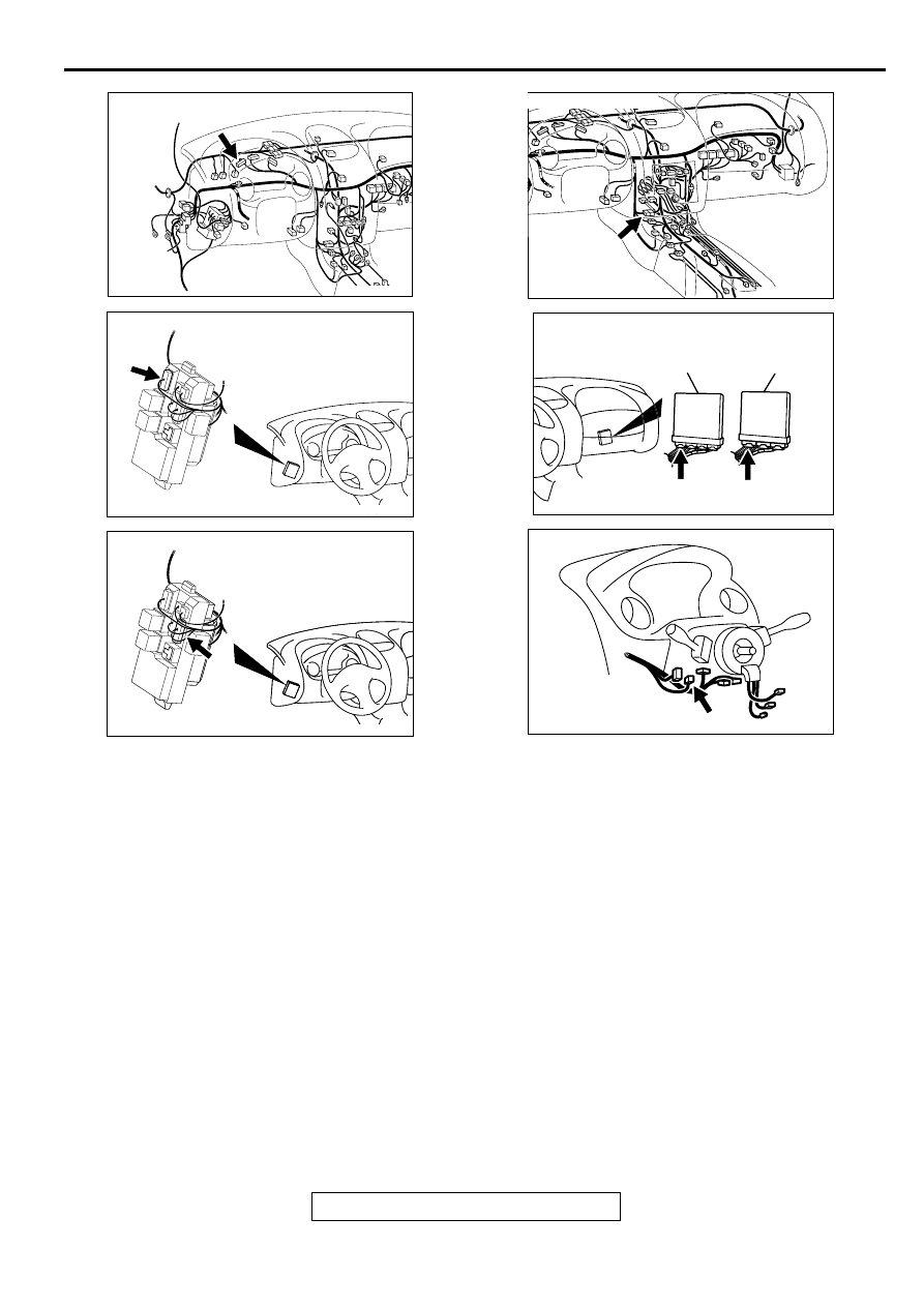
STEP 5. Check connector C-51 at ECM <M/T> or connector
C-52 at PCM <A/T> for damage.
Q: Is the connector in good condition?
YES : Go to Step 6.
NO : Repair or replace it. Refer to GROUP 00E, Harness
Connector Inspection (
). Then confirm that
the malfunction symptom is eliminated.
AK000364AC
56 55 54 53 52 5150 49 48
47 46 45 44 43 42 41
C-41 HARNESS
SIDE CONNECTOR
AK000225
CONNECTOR : C-51<M/T>, C-52<A/T>
C-52
C-51
PCM<A/T>
ECM<M/T>
AJ
MULTIPORT FUEL INJECTION (MFI) DIAGNOSIS
TSB Revision
MULTIPORT FUEL INJECTION (MFI) <3.0L ENGINE>
13B-420
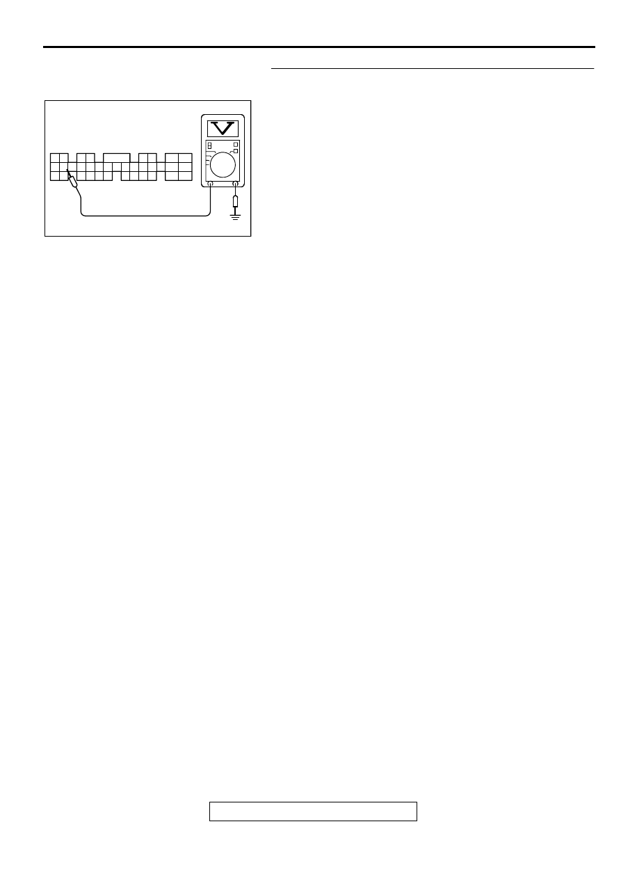
STEP 6. Check the power supply voltage ECM connector
C-51 <M/T> or PCM connector C-52 <A/T>.
(1) Disconnect the connector C-51 <M/T> or C-52 <A/T> and
measure at the harness side.
(2) Turn the ignition switch to the "ON" position.
(3) Measure the voltage between terminal 22 and ground.
•
Voltage should be battery positive voltage.
(4) Turn the ignition switch to the "LOCK" (OFF) position.
Q: Is the voltage normal?
YES : Replace the ECM or PCM. Then confirm that the
malfunction symptom is eliminated.
NO : Check harness connectors C-28 at intermediate
connector for damage, and repair or replace as
required. Refer to GROUP 00E, Harness Connector
Inspection (
). If intermediate connectors is in
good condition, repair harness wire between
combination meter connector C-41 terminal 41 and
ECM connector C-51 terminal 22 <M/T> or PCM
connector C-52 terminal 22 <A/T> because of open
circuit. Then confirm that the malfunction symptom is
eliminated.
AKX01508AE
1
2
3
4
5
6
7
8
9
10
11
12
13
14
15
16
17
18
19
20
21
22
23
24
25
26
27
28
29
30
31
32
33
34
35
C-51<M/T>,C-52<A/T>
HARNESS SIDE
CONNECTOR
MULTIPORT FUEL INJECTION (MFI) DIAGNOSIS
TSB Revision
MULTIPORT FUEL INJECTION (MFI) <3.0L ENGINE>
13B-421
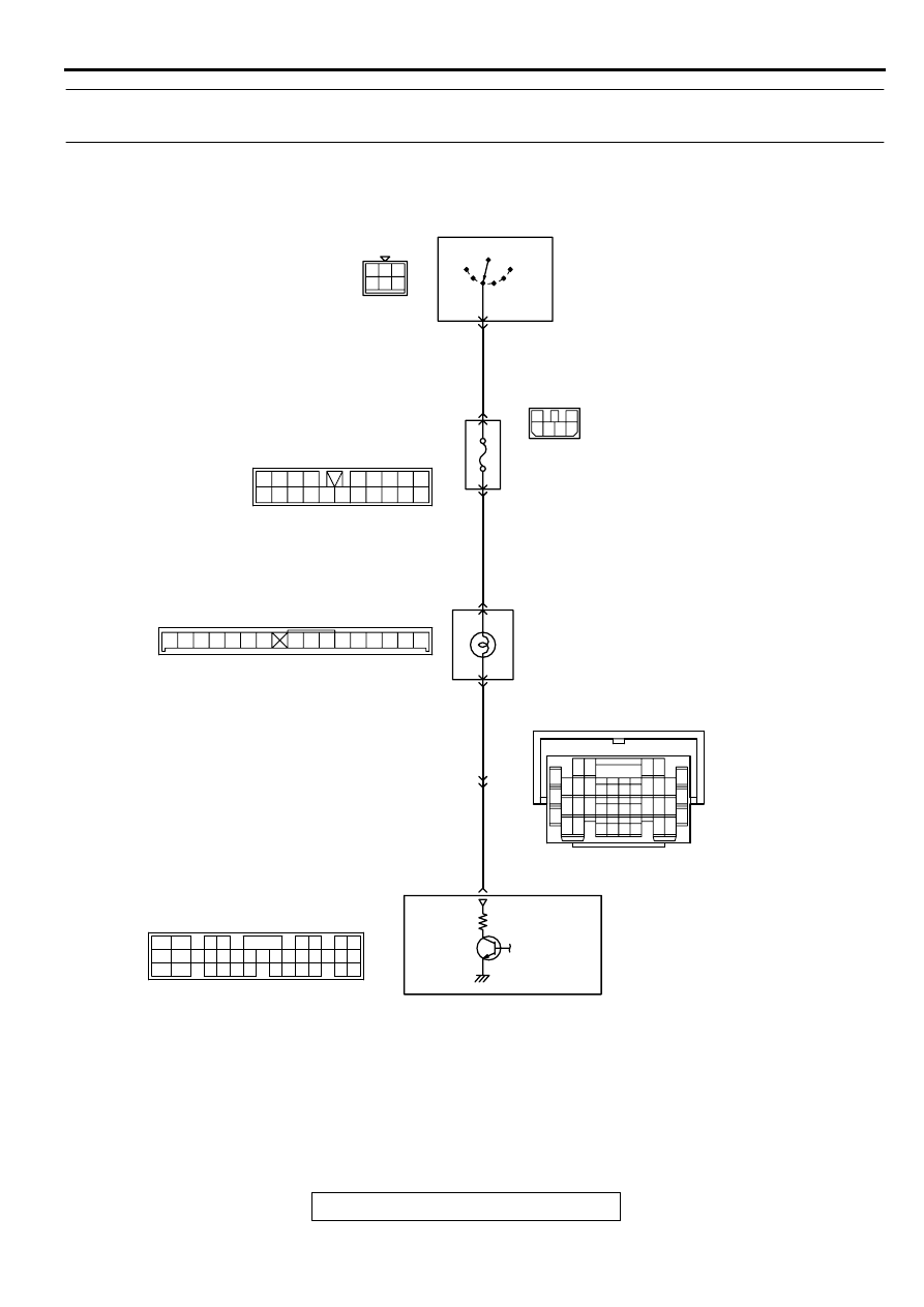
INSPECTION PROCEDURE 4: The Service Engine Soon/Malfunction Indicator Lamp Remains
Illuminated and Never Goes Out.
AK000712
3
2
4 5 6
1 2 3
4 5 6
GREEN
1
RED
-
YELL
OW
RED
-
YELL
OW
BL
ACK
-
WHITE
R
IG2
ST
LOCK
ACC
IG1
C-101
MU801331
IGNITION
SWITCH
C-87
2
6
6
JUNCTION
BLOCK
52
41
SERVICE ENGINE SOON/
MALFUNCTION INDICATOR LAMP
ENGINE CONTROL
MODULE(ECM)<M/T>
OR
POWERTRAIN CONTROL
MODULE(PCM)<A/T>
21
22
C-104
MU801457
1
6
4
5
11
10
12 13
15
17
16
14
19
18
8 9
7
20
2 3
44 45
41
46 47
42 43
49 50 5152
48
55 56
54
53
C-41
C-28
7 8
5
3 4
35
34
10 11 12
2122 23 24
13 14 15
25 26 27
16
28
17
18 19 20
29
30 31
32 33
36 37
38
9
1 2
6
C-51<M/T>,C-52<A/T>
(MU803784)
2
3 4
5 6
7 8
9
11 12 13 14 15 16 17 18 19 20
30
21 22 23
24 25
26 27 28 29
3132 33
34 35
1
10
MULTIPORT FUEL INJECTION (MFI) DIAGNOSIS
TSB Revision
MULTIPORT FUEL INJECTION (MFI) <3.0L ENGINE>
13B-422
CIRCUIT OPERATION
•
The service engine soon/malfunction indicator
lamp power is supplied from the ignition switch.
•
The ECM <M/T> or PCM <A/T> controls the
ground of the service engine soon/malfunction
indicator lamp by turning the power transistor in
the ECM <M/T> or PCM <A/T> ON and OFF.
COMMENT
•
In cases such as the above, the cause is
probably that the ECM <M/T> or PCM <A/T> is
detecting a problem in a sensor or actuator, or
that one of the malfunctions listed at right has
probably occurred.
TROUBLESHOOTING HINTS (The most likely
causes for this case:)
•
Short-circuit between the service engine soon/
malfunction indicator lamp and ECM <M/T> or
PCM <A/T>.
•
Malfunction of the ECM <M/T> or PCM <A/T>.
DIAGNOSIS
Required Special Tool:
MB991502:Scan Tool (MUT-II)
AK000312AI
CONNECTOR:C-41
AK000315
CONNECTOR:C-101
AC
AK000311
AK000311
CONNECTOR:C-104
AC
AK000733AC
CONNECTOR:C-28
AK000225
CONNECTOR : C-51<M/T>, C-52<A/T>
C-52
C-51
PCM<A/T>
ECM<M/T>
AJ
AK000219
CONNECTOR:C-87
AC
Нет комментариевНе стесняйтесь поделиться с нами вашим ценным мнением.
Текст