Mitsubishi Eclipse / Eclipse Spyder (2000-2002). Service and repair manual — part 139
MULTIPORT FUEL INJECTION (MFI) DIAGNOSIS
TSB Revision
MULTIPORT FUEL INJECTION (MFI) <2.4L ENGINE>
13A-255
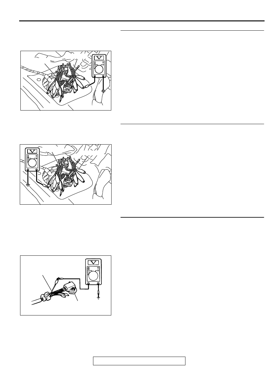
STEP 3. Check the 5-volt supply circuit voltage at
intermediate connector D-16.
(1) Do not disconnect intermediate connector D-16.
(2) Use special tools (MB991658 and MB991709) to connect
terminals 5, 6 and 8 between connectors of the
intermediate connector, respectively.
(3) Turn the ignition switch to the "ON" position.
(4) Measure the voltage between terminal 8 and ground by
backprobing.
•
Voltage should be between 4.8 and 5.2 volts.
(5) Turn the ignition switch to the "LOCK" (OFF) position.
Q: Is the multi-meter reading within the specified value?
YES : Go to Step 4.
NO : Go to Step 11.
STEP 4. Check the ground circuit voltage at intermediate
connector D-16.
(1) Do not disconnect intermediate connector D-16.
(2) Use special tools (MB991658 and MB991709) to connect
terminals 5, 6 and 8 between connectors of the
intermediate connector, respectively.
(3) Turn the ignition switch to the "ON" position.
(4) Measure the voltage between terminal 6 and ground by
backprobing.
•
Voltage should be between 0.5 volts or less.
(5) Turn the ignition switch to the "LOCK" (OFF) position.
Q: Is the multi-meter reading within the specified value?
YES : Go to Step 5.
NO : Go to Step 15.
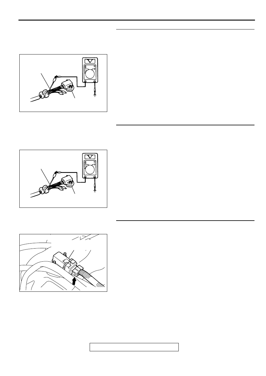
STEP 5. Check the output circuit voltage at fuel tank
differential pressure connector D-18.
(1) Remove the center pipe.
(2) Remove the fuel band assembly, tilt the fuel tank.
(3) Disconnect fuel tank differential pressure sensor connector
D-18.
(4) Use special tool (MB991658) to connect terminals 1, 2 and
3 of the disconnected sensor connector and those of the
harness side connector, respectively.
(5) Turn the ignition switch to the "ON" position.
(6) Remove the fuel cap.
(7) Measure the voltage between terminal 1 and ground by
backprobing.
•
Voltage should be between 2.0 and 3.0 volts.
(8) Turn the ignition switch to the "LOCK" (OFF) position.
Q: Is the multi-meter reading within the specified value?
YES : Go to Step 17.
NO : Go to Step 6.
AC002080
MB991709
MB991658
AB
AC002079 AB
MB991709
MB991658
AC002081AB
MB991658
FUEL TANK DIFFERENTIAL
PRESSURE SENSOR
MULTIPORT FUEL INJECTION (MFI) DIAGNOSIS
TSB Revision
MULTIPORT FUEL INJECTION (MFI) <2.4L ENGINE>
13A-256
STEP 6. Check the 5-volt supply circuit voltage at fuel tank
differential pressure sensor connector D-18.
(1) Do not disconnect fuel tank differential pressure sensor
connector D-18.
(2) Use special tool (MB991658) to connect terminals 1, 2 and
3 of the disconnected sensor connector and those of the
harness side connector, respectively.
(3) Turn the ignition switch to the "ON" position.
(4) Measure the voltage between terminal 3 and ground by
backprobing.
•
Voltage should be between 4.8 and 5.2 volts.
(5) Turn the ignition switch to the "LOCK" (OFF) position.
Q: Is the multi-meter reading within the specified value?
YES : Go to Step 7.
NO : Go to Step 17.
STEP 7. Check the ground circuit voltage at fuel tank
differential pressure sensor connector D-18.
(1) Disconnect fuel tank differential pressure sensor connector
D-18.
(2) Use special tool (MB991658) to connect terminals 1, 2 and
3 of the disconnected sensor connector and those of the
harness side connector, respectively.
(3) Turn the ignition switch to the "ON" position.
(4) Measure the voltage between terminal 2 and ground by
backprobing.
•
Voltage should be between 0.5 volts or less.
(5) Turn the ignition switch to the "LOCK" (OFF) position.
Q: Is the multi-meter reading within the specified value?
YES : Go to Step 8.
NO : Go to Step 17.
STEP 8. Check fuel tank differential pressure sensor
connector D-18 for damage.
(1) Disconnect fuel tank differential pressure sensor connector
D-18.
Q: Is there any failure at fuel tank differential pressure
sensor connector D-18?
YES : Go to Step 9.
NO : Repair or replace it. Refer to GROUP 00E, Harness
Connector Inspection
. Then go to Step 26.
AC002081AB
MB991658
FUEL TANK DIFFERENTIAL
PRESSURE SENSOR
AC002081AB
MB991658
FUEL TANK DIFFERENTIAL
PRESSURE SENSOR
AC002041AB
CONNECTOR: D-18
FUEL TANK DIFFERENTIAL
PRESSURE SENSOR
MULTIPORT FUEL INJECTION (MFI) DIAGNOSIS
TSB Revision
MULTIPORT FUEL INJECTION (MFI) <2.4L ENGINE>
13A-257
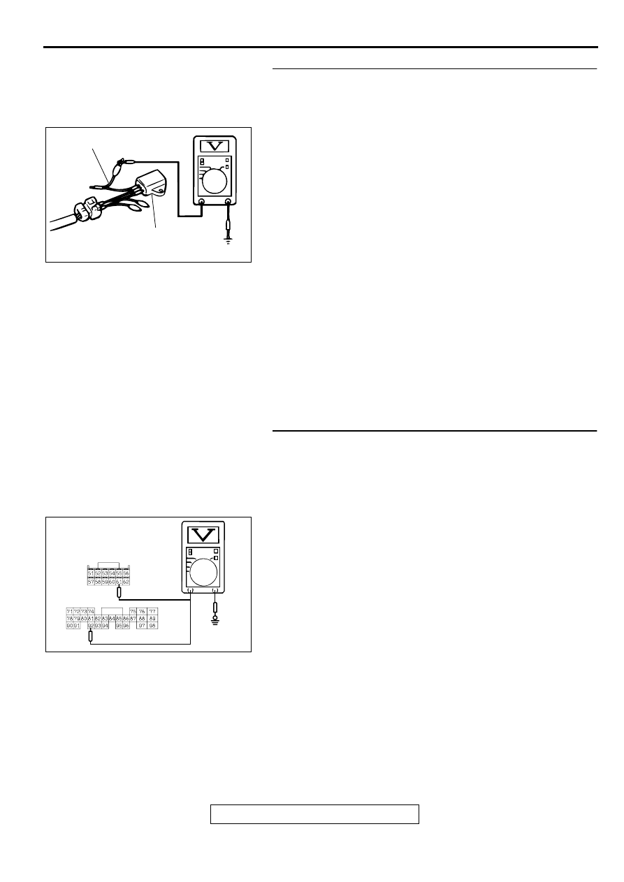
STEP 9. Check the output voltage at fuel tank differential
pressure sensor connector D-18.
(1) Disconnect fuel tank differential pressure sensor connector
D-18.
(2) Use special tool (MB991658) to connect terminals 2 and 3
of the disconnected sensor connector and those of the
harness side connector, respectively.
(3) Turn the ignition switch to the "ON" position.
(4) Remove the fuel cap.
(5) Measure the voltage between terminal 1 and ground by
backprobing.
•
Voltage should be between 2.0 and 3.0 volts.
(6) Turn the ignition switch to the "LOCK" (OFF) position.
Q: Is the multi-meter reading within the specified value?
YES : Check connectors D-16, C-90, C-28, C-56 <M/T> or
C-57 <A/T> and repair or replace as required. Refer
to GROUP 00E, Harness Connector Inspection
. If connectors D-16, C-90, C-28, C-56 <M/T>
or C-57 <A/T> are in good condition, check the
harness between fuel tank differential pressure
sensor connector D-18 and ECM connector C-56 <M/
T> or PCM connector C-57 <A/T> for short circuit to
ground, then repair if necessary. Then go to Step 26.
NO : Replace the fuel tank differential pressure sensor.
Then go to Step 26.
STEP 10. Check the output circuit voltage at ECM
connector C-56 <M/T> or PCM connector C-57 <A/T>.
(1) Do not disconnect the ECM connector C-56 <M/T> or PCM
connector C-57 <A/T>.
(2) Turn the ignition switch to the "ON" position.
(3) Remove the fuel cap.
(4) Measure the voltage between terminal 61 <M/T> or terminal
92 <A/T> and ground by backprobing.
•
Voltage should be between 2.0 and 3.0 volts.
(5) Turn the ignition switch to the "LOCK" (OFF) position.
Q: Is the multi-meter reading within the specified value?
YES : Go to Step 18.
NO : Check connectors D-16, C-90, C-28, C-56 <M/T> or
C-57 <A/T> and repair or replace as required. Refer
to GROUP 00E, Harness Connector Inspection
. If connectors D-16, C-90, C-28, C-56 <M/T>
or C-57 <A/T> are in good condition, check the
harness between intermediate connector D-16 and
ECM connector C-56 <M/T> or PCM connector C-57
<A/T> for open circuit or damage. Then repair if
necessary. Then go to Step 26.
ACX01760AB
MB991658
FUEL TANK DIFFERENTIAL
PRESSURE SENSOR
AC002551AC
<M/T> C-56
<A/T> C-57
HARNESS SIDE
CONNECTOR
MULTIPORT FUEL INJECTION (MFI) DIAGNOSIS
TSB Revision
MULTIPORT FUEL INJECTION (MFI) <2.4L ENGINE>
13A-258
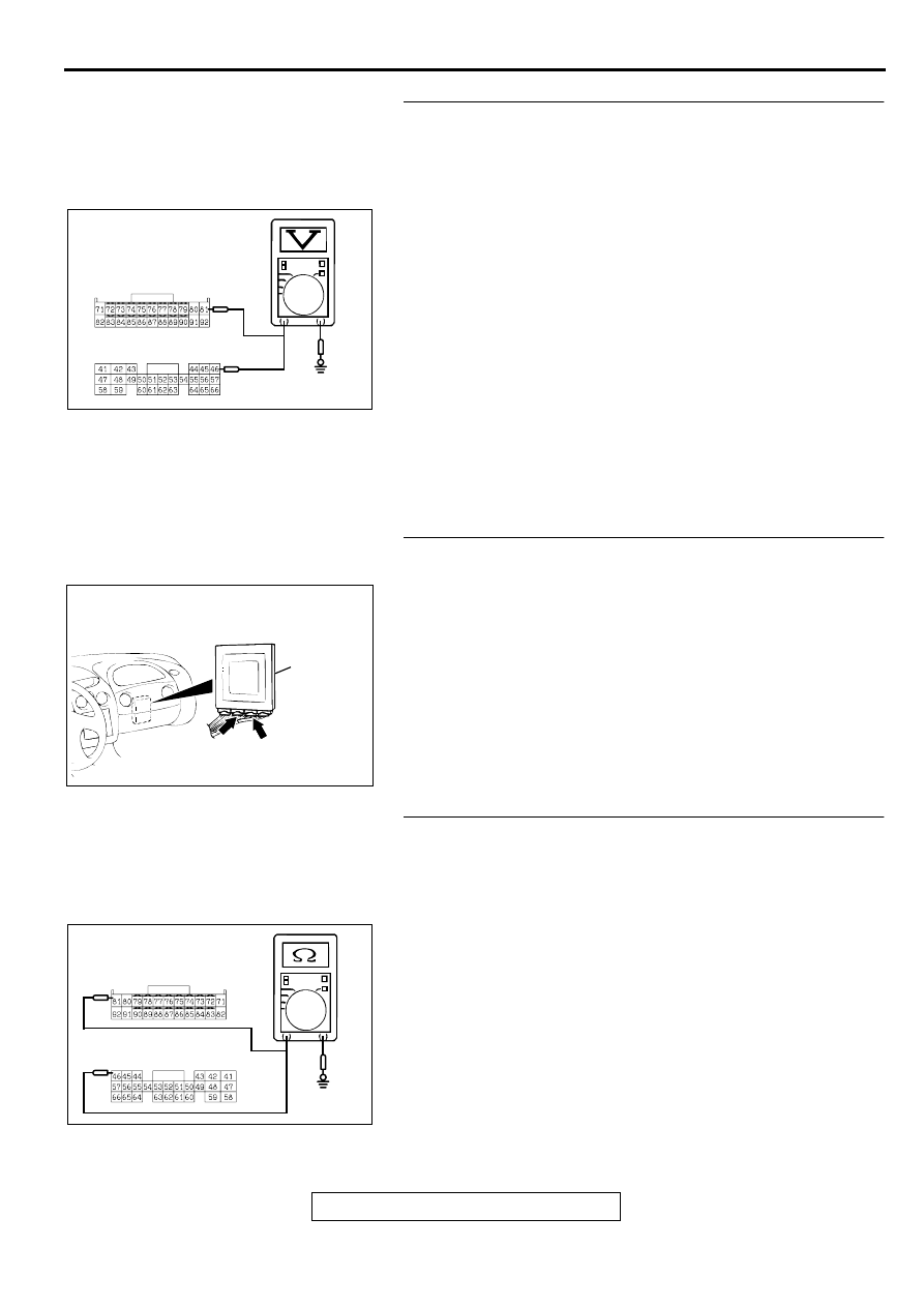
STEP 11. Check the 5-volt supply circuit voltage at ECM
connector C-60 <M/T> or PCM connector C-54 <A/T>.
(1) Do not disconnect ECM connector C-60 <M/T> or PCM
connector C-54 <A/T>.
(2) Turn the ignition switch to the "ON" position.
(3) Measure the voltage between terminal 81 <M/T> or terminal
46 <A/T> and ground by backprobing.
•
Voltage should be between 4.8 and 5.2 volts.
(4) Turn the ignition switch to the "LOCK" (OFF) position.
Q: Is the multi-meter reading within the specified value?
YES : Check connectors D-16, C-90, C-28, C-60 <M/T> or
C-54 <A/T> and repair or replace as required. Refer
to GROUP 00E, Harness Connector Inspection
. If connectors D-16, C-90, C-28, C-60 <M/T>
or C-54 <A/T> are in good condition, check the
harness between intermediate connector D-16 and
ECM connector C-60 <M/T> or PCM connector C-54
<A/T> for open circuit or damage. Then repair if
necessary. Then go to Step 26.
NO : Go to Step 12.
STEP 12. Check ECM connector C-60 <M/T> or PCM
connector C-54 <A/T> for damage.
(1) Disconnect ECM connector C-60 <M/T> or PCM connector
C-54 <A/T>.
Q: Is there any failure at ECM connector C-60 <M/T> or
PCM connector C-54 <A/T>?
YES : Repair or replace it. Refer to GROUP 00E, Harness
Connector Inspection
. Then go to Step 26.
NO : Go to Step 13.
STEP 13. Check the sensor power supply line for short
circuit to ground at ECM connector C-60 <M/T> or PCM
connector C-54 <A/T>.
(1) Disconnect ECM connector C-60 <M/T> or PCM connector
C-54 <A/T> and measure at the harness side.
(2) Check for the continuity between terminal 81 <M/T> or
terminal 46 <A/T> and ground.
•
There should be 2 ohms or more.
Q: Does the multi-meter reading exceed the specified
value?
YES : Replace ECM or PCM. Then go to Step 26.
NO : Go to Step 14.
AC002552
HARNESS SIDE
CONNECTOR
<M/T> C-60
<A/T> C-54
AC
AC001689
CONNECTOR: C-60 <M/T>, C-54 <A/T>
ECM <M/T>
OR
PCM <A/T>
AL
C-54
<A/T>
C-60
<M/T>
AC002553
HARNESS SIDE
CONNECTOR
<M/T> C-60
<A/T> C-54
AC
Нет комментариевНе стесняйтесь поделиться с нами вашим ценным мнением.
Текст