Mitsubishi Eclipse / Eclipse Spyder (2000-2002). Service and repair manual — part 545
SPECIAL TOOLS
TSB Revision
REAR AXLE
27-3
SYMPTOM PROCEDURES
M1271004400103
INSPECTION PROCEDURE 1: Abnormal Noise
DIAGNOSIS
STEP 1. Check the wheel nut for looseness.
Q: Are the wheel nuts loosened?
YES :
Tighten the nuts, then go to Step3.
NO :
Go to Step 2.
STEP 2. Check the wheel bearing for wear or
damage.
Q: Is the wheel bearing in good condition?
YES :
Go to step 3.
NO :
Replace the part, then go to Step 4.
STEP 3. Check the brake disc for bent or
distortion.
Q: Is the brake disc in good condition?
YES :
Go to Step 4.
NO :
Replace the part, then go to Step 4.
STEP 4. Check trouble symptoms.
Q: Are any noises generated?
YES :
Return to Step 1.
NO :
This diagnosis is complete.
SPECIA L TO O LS
M1271000600064
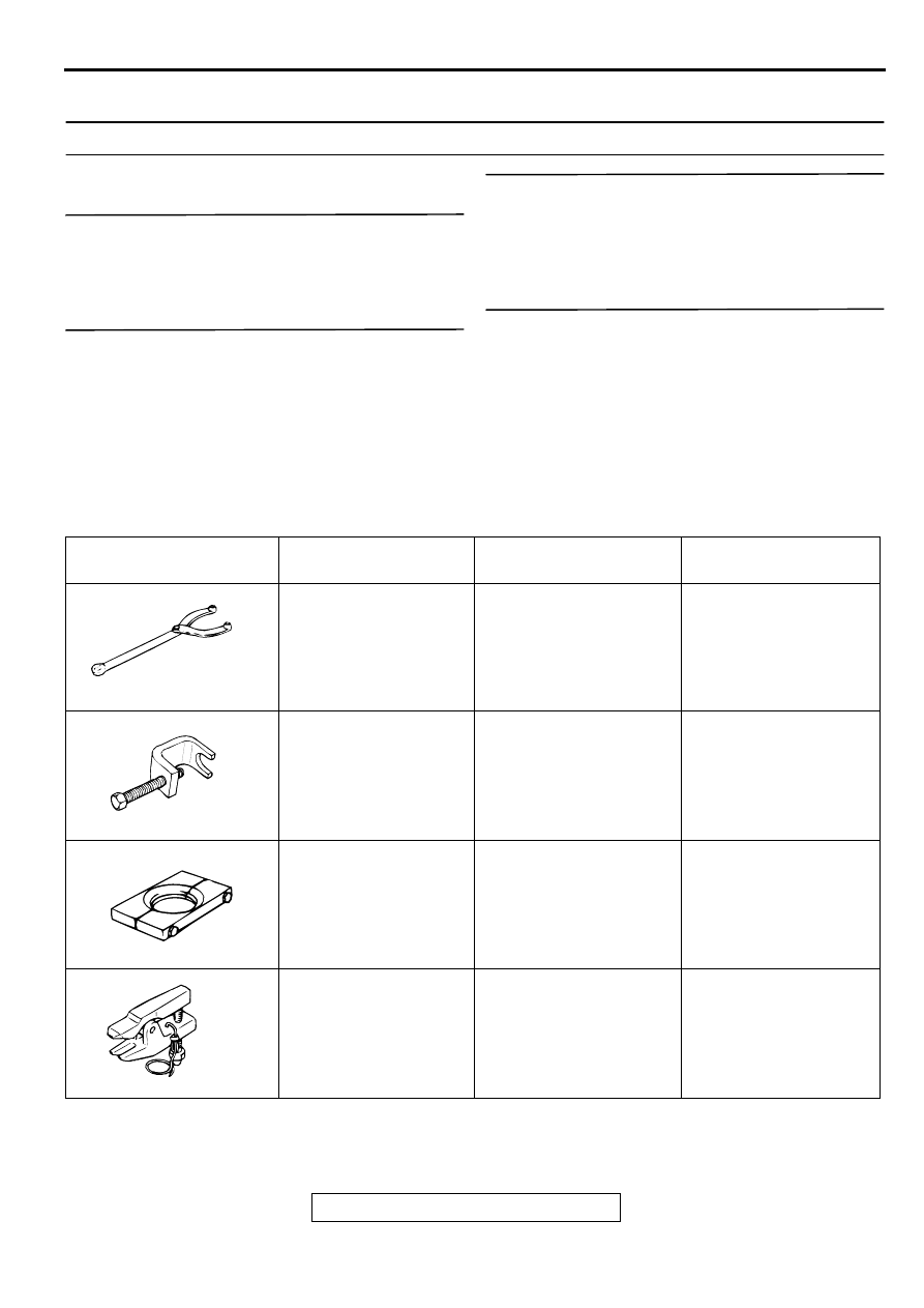
TOOL
TOOL NUMBER AND
NAME
SUPERSESSION
APPLICATION
MB990767
End yoke holder
MB990767-1
Hub fixing
MB991618
Hub bolt remover
General service tool
Hub bolt removal
MB991248
Inner shaft remover
Tool not available
ABS rotor removal
MB990635 or MB991113
Steering linkage puller
MB991113-1, MB990635-
01 or General service tool
Ball joint disconnection
MB990767
MB991618
MB991248
MB990635
ON-VEHICLE SERVICE
TSB Revision
REAR AXLE
27-4
O N -VEH IC LE SERVIC E
WHEEL BEARING END PLAY CHECK
M1271000900076
1. For vehicles with rear disc brakes, remove the caliper
assembly, suspend the caliper assembly with a wire and
remove the brake disc.
2. For vehicles with rear drum brakes, remove the brake drum.
3. Check the bearing's end play.
Place a dial gauge against the hub surface; then move the
hub in the axial direction and check whether or not there is
end play.
Limit: 0.05 mm (0.002 inch)
4. If the play exceeds the limit value, replace the rear hub
assembly.
REAR HUB ROTARY-SLIDING RESISTANCE
CHECK
M1271001100051
1. For vehicles with rear disc brakes, remove the caliper
assembly, suspend the caliper assembly with a wire and
remove the brake disc.
2. For vehicles with rear drum brakes, remove the brake drum.
3. After turning the hub a few times to seat the bearing, wind a
rope around the hub bolt and turn the hub by pulling at a 90
degree angle with a spring scale. Measure to determine
whether or not the rotary-sliding resistance of the rear hub is
at the limit value.
Limit: 18 N
⋅
m (13 ft-lb)
4. If the rotary-sliding resistance exceeds the limit value,
replace the rear hub assembly.
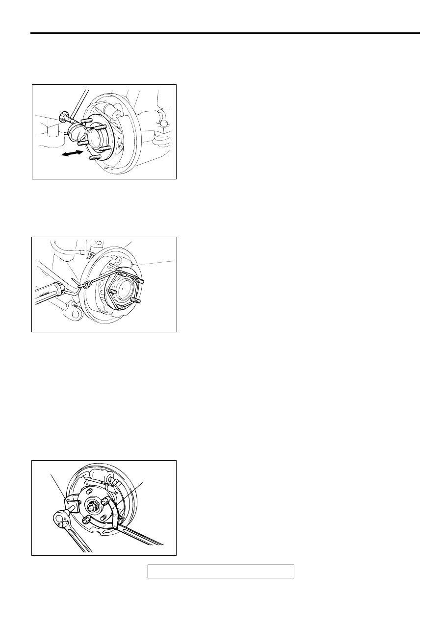
HUB BOLT REPLACEMENT
M1271001000054
Required Special Tools:
•
MB990767: End Yoke Holder
•
MB991618: Hub Bolt Remover
1. For vehicles with rear disc brakes, remove the caliper
assembly, suspend the caliper assembly with a wire and
remove the brake disc.
2. For vehicles with rear drum brake, remove the brake drum.
3. Pull the hub bolt out using special tools MB990767 and
MB991618.
NOTE: For vehicles with drum brakes, the hub bolts should
be removed near the retainer spring installation position in
order to maintain enough clearance for removal.
AC001180
AC001181
AC001182
MB990767
AB
MB991618
REAR AXLE HUB ASSEMBLY
TSB Revision
REAR AXLE
27-5
4. Install the plain washer to the new hub bolt, and install the
bolt with a nut.
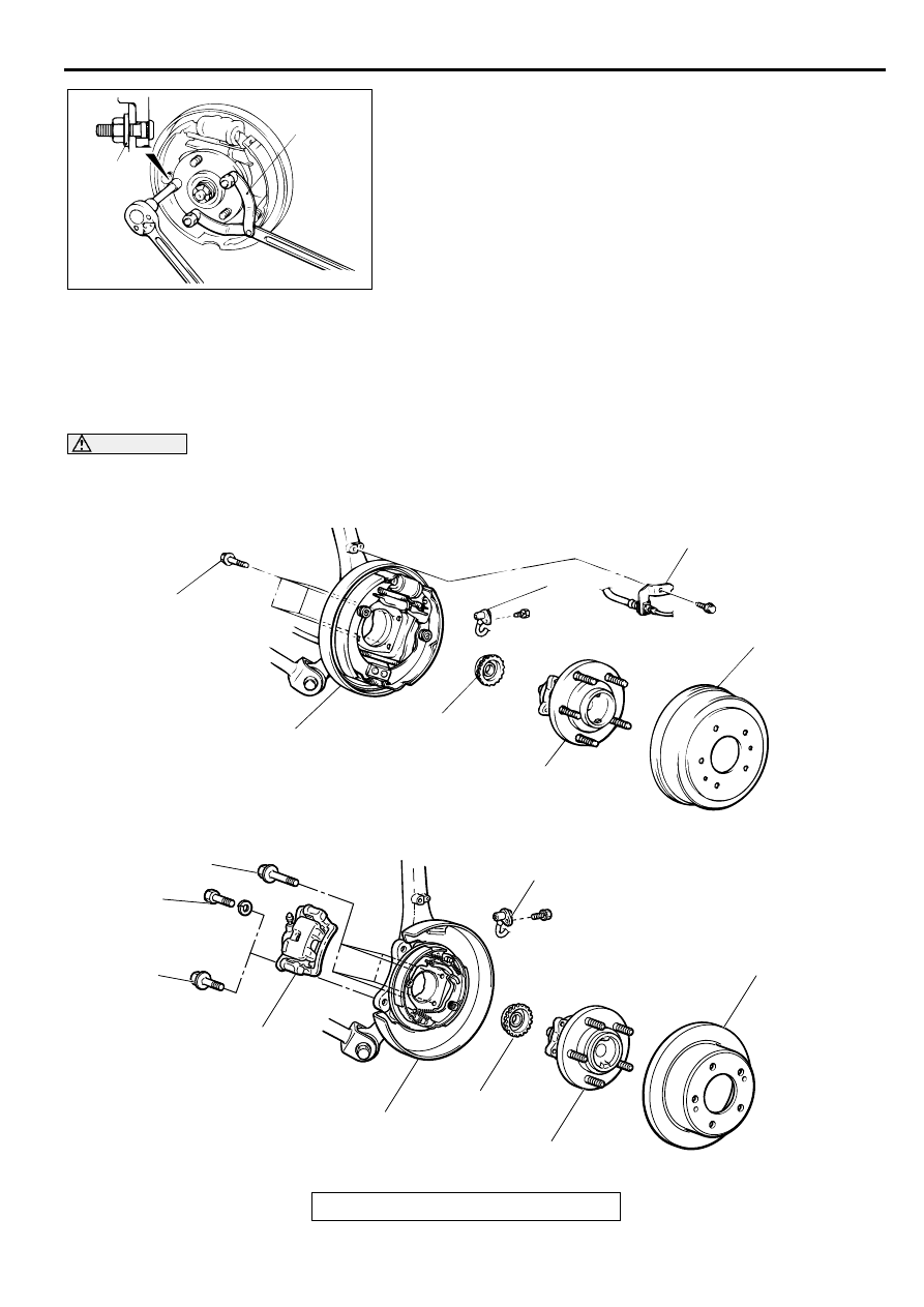
REA R A XLE H U B A SSEM B LY
REMOVAL AND INSTALLATION
M1271002000057
CAUTION
The rear hub unit bearing should not be dismantled.
AC001183
MB990767
AB
PLAIN
WASHER
AC000977
<VEHICLES WITH REAR DRUM BRAKE>
<VEHICLES WITH REAR DISC BRAKE>
81 ± 7 N·m
60 ± 5 ft-lb
81 ± 7 N·m
60 ± 5 ft-lb
55 ± 5 N·m
41 ± 3 ft-lb
60 ± 5 N·m
45 ± 3 ft-lb
1
8
7
6
5
3
1
8
7
6
4
2
AD
REAR AXLE HUB ASSEMBLY
TSB Revision
REAR AXLE
27-6
Required Special Tool:
•
MB991248: Inner Shaft Remover
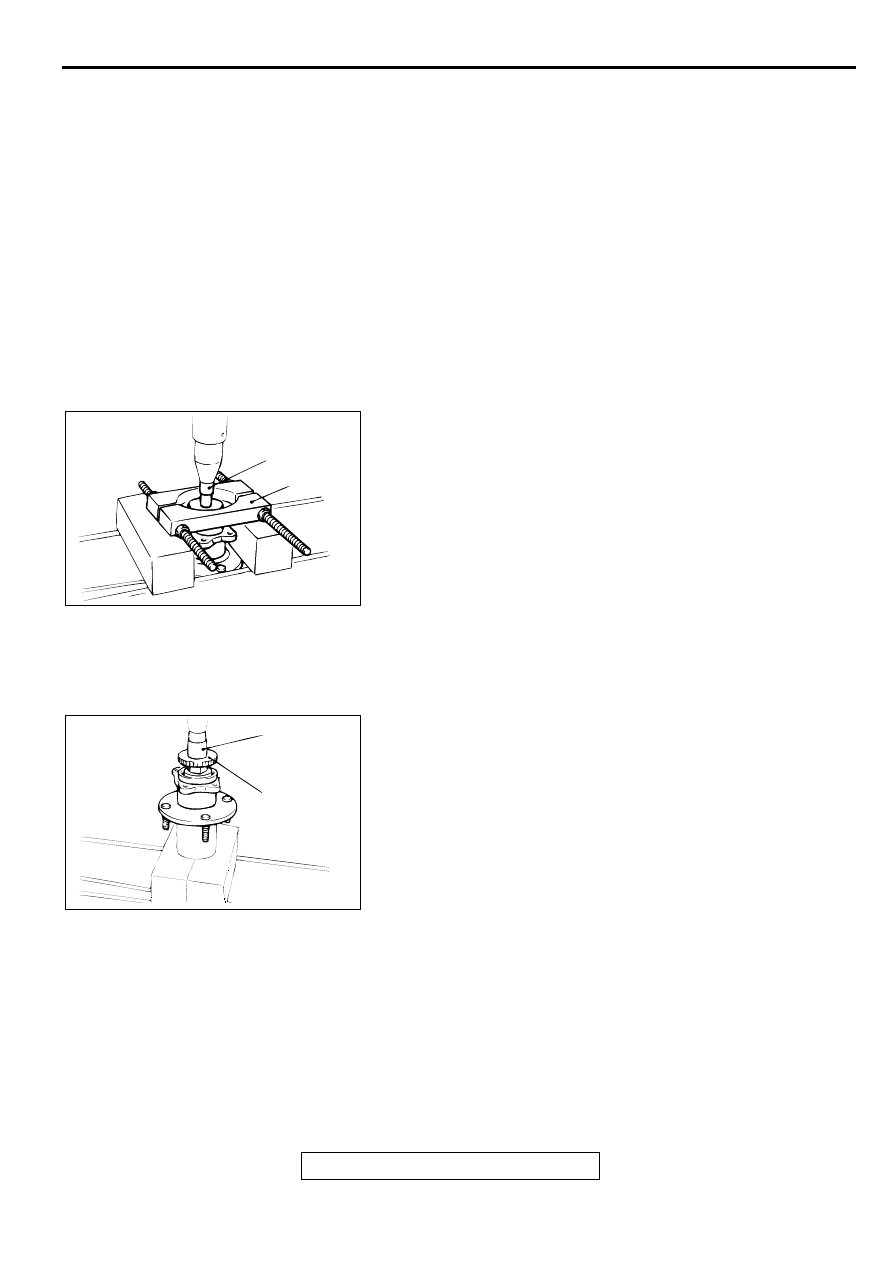
REMOVAL SERVICE POINTS
<<A>> CALIPER ASSEMBLY REMOVAL
Remove the caliper assembly and suspend it with a wire.
<<B>> ABS ROTOR REMOVAL
Use special tool MB991248 to remove the ABS rotor.
<<C>> BACKING PLATE REMOVAL
Remove the backing plate and suspend it.
INSTALLATION SERVICE POINT
>>A<< ABS ROTOR INSTALLATION
Install the ABS rotor as shown in the illustration.
INSPECTION
M1271002100065
•
Check the oil seal for crack or damage.
•
Check the ABS rotor for chipped teeth.
REMOVAL STEPS
1.
REAR WHEEL SPEED SENSOR
<VEHICLES WITH ABS> (REFER
TO GROUP 35B
<<A>>
2.
CALIPER ASSEMBLY
3.
BRAKE DRUM
4.
BRAKE DISC
5.
BRAKE HOSE INSTALLATION
BRACKET
6.
REAR HUB ASSEMBLY
<<B>> >>A<<
7.
ABS ROTOR <VEHICLES WITH
ABS>
<<C>>
8.
BACKING PLATE
REMOVAL STEPS (Continued)
AC001185
SOCKET
AB
MB991248
AC001186 AB
ABS ROTOR
SOCKET
Нет комментариевНе стесняйтесь поделиться с нами вашим ценным мнением.
Текст