Mitsubishi Eclipse / Eclipse Spyder (2000-2002). Service and repair manual — part 543
DRIVE SHAFT ASSEMBLY
TSB Revision
FRONT AXLE
26-21
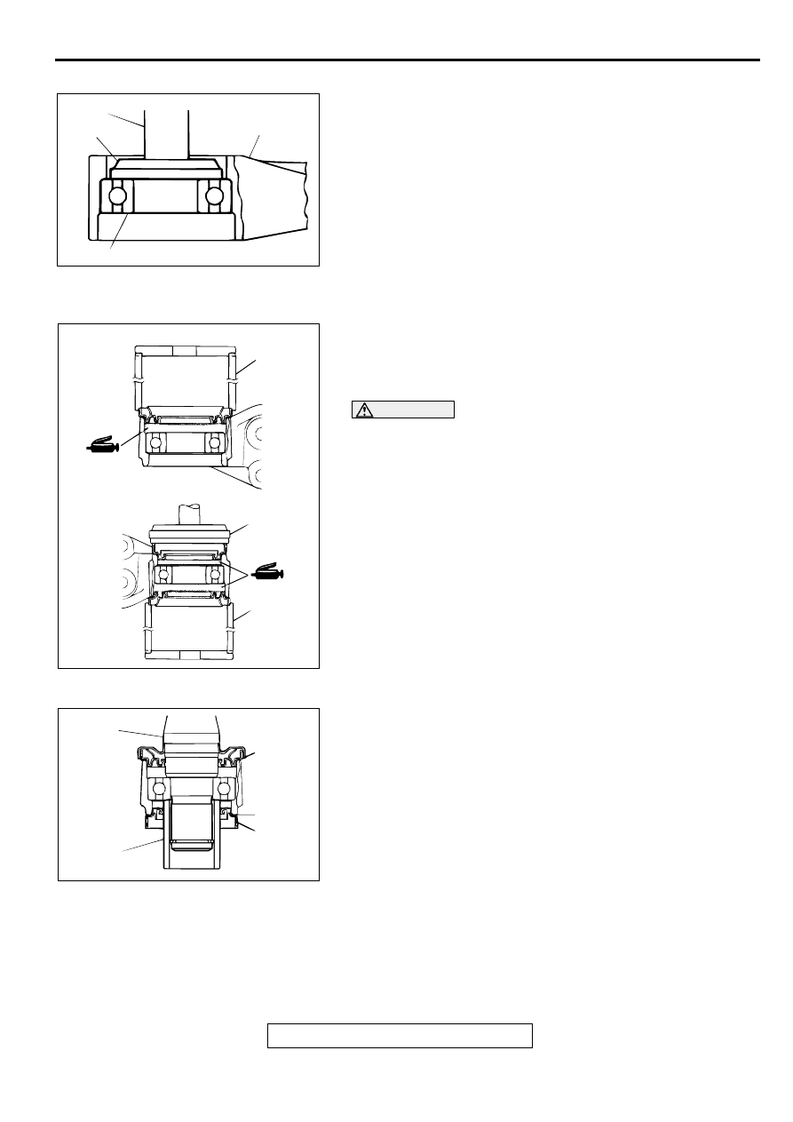
>>C<< CENTER BEARING INSTALLATION
Use special tools MB990930 and MB990938 to press the
center bearing into the center bearing bracket.
>>D<< DUST SEAL INNER/DUST SEAL OUTER
INSTALLATION
1. Pack multipurpose grease in the places shown in the figure.
Quantity:
14
−
20 g (0.5
−
0.7 oz) <Dust seal inner>
8
−
12 g (0.3
−
0.4 oz) <Dust seal outer>
CAUTION
Do not damage the rubber portion of the dust seal outer
surface when packing the multipurpose grease, otherwise
grease will leak.
2. Use special tools MB990890 and MB990934 to press the oil
seal into the center bearing bracket.
3. Apply multipurpose grease to the lip of the dust seal.
NOTE: Do not apply the specified grease to the outside of
the lip.
>>E<< INNER SHAFT INSTALLATION
Use special tool MB991172 to hold the center bearing inner
race, and then press-in the inner shaft.
AC001168
MB990938
CENTER BEARING
CENTER
BEARING
BRACKET
AB
MB990930
AC001169
DUST SEAL INNER
MB990890
MB990934
MB990890
AB
DUST SEAL OUTER
AC001170
INNER
SHAFT
AB
MB991172
DRIVE SHAFT ASSEMBLY
TSB Revision
FRONT AXLE
26-22
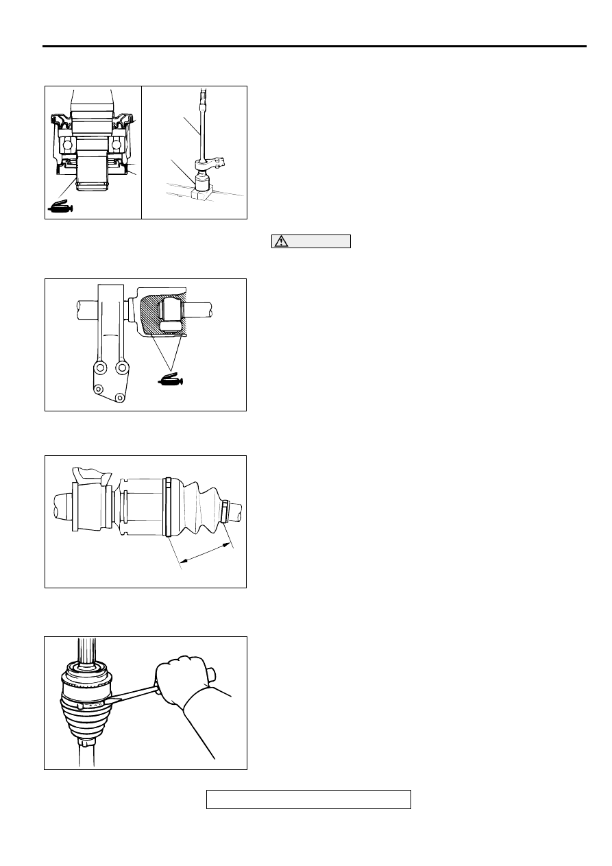
>>F<< TJ CASE AND INNER SHAFT ASSEMBLY
INSTALLATION
1. Apply multipurpose grease to the inner shaft serration, and
then press the inner shaft assembly into the TJ case.
CAUTION
The driveshaft joint uses special grease. Do not mix old
and new or different types of grease.
2. Fill the TJ case with repair kit grease and insert the
driveshaft, and then refill the TJ case with repair kit grease.
Grease quantity:
100
±
10 g (3.5
±
0.4 oz) <2.4L ENGINE>
105
±
10 g (3.7
±
0.4 oz) <3.0L ENGINE>
NOTE: The grease in the repair kit should be divided in half
for use, respectively, at the joint and inside the boot.
>>G<< TJ BOOT BAND (SMALL)/TJ BOOT BAND (LARGE)
INSTALLATION
1. Position the TJ outer race so that the distance between the
boot bands is at the standard value.
Standard value (A): 85
±
3 mm (3.3
±
0.12 inch)
2. Remove part of the TJ outer race to release the air pressure
inside the boot.
BJ BOOT REPLACEMENT
M1261005200071
1. Remove the boot bands (large and small).
NOTE: The BJ boot bands cannot be re-used.
2. Remove the BJ boot.
AC001171
TJ CASE
AB
INNER
SHAFT
ASSEMBLY
AC001172
AC001173AB
A
ACX00982 AB
DRIVE SHAFT ASSEMBLY
TSB Revision
FRONT AXLE
26-23
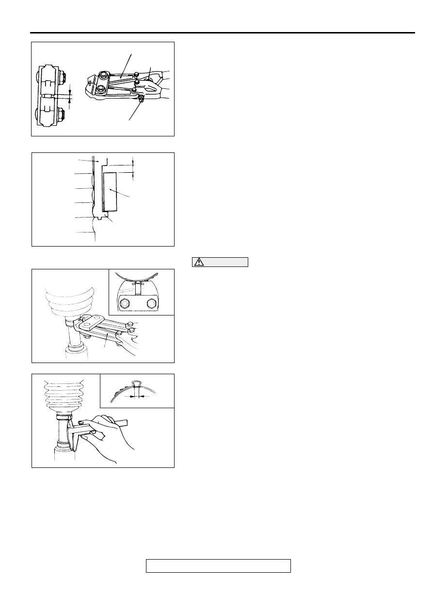
3. Turn the adjusting bolt on the special tool MB991561 so that
the size of the opening (W) is at the standard value.
Standard value (W): 2.9 mm (0.12 inch)
<If it is larger than 2.9 mm (0.12 inch)>
Tighten the adjusting bolt.
<If it is smaller than 2.9 mm (0.12 inch)>
Loosen the adjusting bolt.
NOTE: The value of W will change by approximately 0.7 mm
(0.03 inch) for each turn of the adjusting bolt.
NOTE: The adjusting bolt should not be turned more than
once.
4. Place the BJ boot band (small) against the projection at the
edge of the boot, and then secure it so that there is a
clearance left as shown by (A) in the illustration.
CAUTION
•
Secure the driveshaft in an upright position and clamp
the part of the BJ boot band to be crimped securely in
the jaws of the special tool MB991561.
•
Crimp the BJ boot band until the special tool MB991561
touches the stopper.
5. Use special tool MB991561 to crimp the BJ boot band
(small).
6. Check that crimping amount (B) of the BJ boot band is at the
standard value.
Standard value (B): 2.4
−
2.8 mm (0.10
−
0.11 inch)
ACX00993AB
STOPPER
ADJUSTING BOLT
(W)
MB991561
AC001175
BJ BOOT
A
BJ BOOT BAND
(SMALL)
PROJECTION
AB
ACX00995AB
MB991561
ACX00996AC
B
DRIVE SHAFT ASSEMBLY
TSB Revision
FRONT AXLE
26-24
<If the crimping amount is larger than 2.8 mm (0.11
inch)>
Readjust the value of (W) in step 4 according to the
following formula, and then repeat the operation in
step 6.
[W = 5.5 mm (0.22 inch)
−
B]
Example: If B = 2.9 mm (0.11 inch), then W = 2.6 mm
(0.10 inch).
<If the crimping amount is smaller than 2.4 mm (0.09
inch)>
Remove the BJ boot band, readjust the value of (W) in
step 4 according to the following formula, and then
repeat the operations in steps 5 and 6 using a new BJ
boot band.
[W = 5.5 mm (0.22 inch)
−
B]
Example: If B = 2.3 mm (0.10 inch), then W = 3.2 mm
(0.13 inch).
7. Check that the BJ boot band is not sticking out past the
place where it has been installed. If the BJ boot band is
sticking out, remove it and then repeat the operations in
steps 4 to 6 using a new BJ boot band.
CAUTION
The driveshaft joint uses special grease. Do not mix old
and new grease or different types of grease.
8. Fill the inside of the BJ boot with the specified amount of the
repair kit grease.
Grease quantity:
<2.4L ENGINE> 110
±
10 g (3.9
±
0.4 oz)
<3.0L ENGINE> 120
±
10 g (4.2
±
0.4 oz)
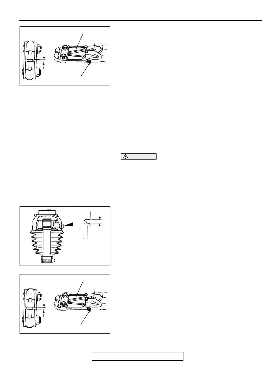
9. Install the BJ boot band (large) so that clearance (C)
between it and the BJ housing is at the standard value.
Standard value (C): 0.1
−
1.55 mm (0.004
−
0.061 inch)
10.Follow the same procedure as in step 3 to adjust the size of
the opening (W) on special tool MB991561 so that it is at the
standard value.
Standard value (W): 3.2 mm (0.13 inch)
ACX00993AB
STOPPER
ADJUSTING BOLT
(W)
MB991561
AC001176
C
AB
ACX00993AB
STOPPER
ADJUSTING BOLT
(W)
MB991561
Нет комментариевНе стесняйтесь поделиться с нами вашим ценным мнением.
Текст