Mitsubishi Eclipse / Eclipse Spyder (2000-2002). Service and repair manual — part 109
MULTIPORT FUEL INJECTION (MFI) DIAGNOSIS
TSB Revision
MULTIPORT FUEL INJECTION (MFI) <2.4L ENGINE>
13A-135
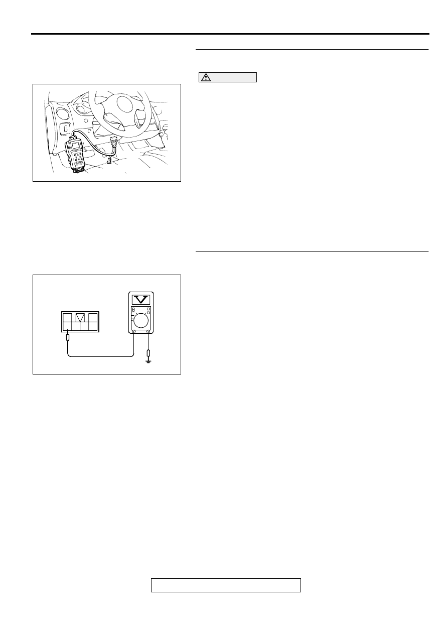
STEP 1. Using scan tool MB991502, check data list item 59:
Heated Oxygen Sensor (rear).
CAUTION
To prevent damage to scan tool MB991502, always turn the
ignition switch to the "LOCK" (OFF) position before
connecting or disconnecting scan tool MB991502.
(1) Connect scan tool MB991502 to the data link connector.
(2) Start the engine and run at idle.
(3) Set scan tool MB991502 to the data reading mode for item
59, Heated Oxygen Sensor (rear).
•
Warming up the engine. When the engine is revved, the
output voltage should repeat 0 volt and 0.6 to 1.0 volt
alternately.
(4) Turn the ignition switch to the "LOCK" (OFF) position.
Q: Is the sensor operating properly?
YES : It can be assumed that this malfunction is intermittent.
Refer to GROUP 00, How to Use Troubleshooting/
Inspection Service Points (
NO : Go to Step 2.
STEP 2. Check the sensor output voltage at heated oxygen
sensor (rear) connector C-23 by backprobing.
(1) Do not disconnect the connector C-23.
(2) Start the engine and run at idle.
(3) Measure the voltage between terminal 3 and ground by
backprobing.
•
Warming up the engine. When the engine is revved, the
output voltage should repeat 0 volt and 0.6 to 1.0 volt
alternately.
(4) Turn the ignition switch to the "LOCK" (OFF) position.
Q: Is the voltage normal?
YES : Go to Step 3.
NO : Go to Step 7.
AKX01177
16 PIN
MB991502
AB
AK000291
C-23 CONNECTOR
HARNESS SIDE VIEW
1
2
3 4 5 6
AD
MULTIPORT FUEL INJECTION (MFI) DIAGNOSIS
TSB Revision
MULTIPORT FUEL INJECTION (MFI) <2.4L ENGINE>
13A-136
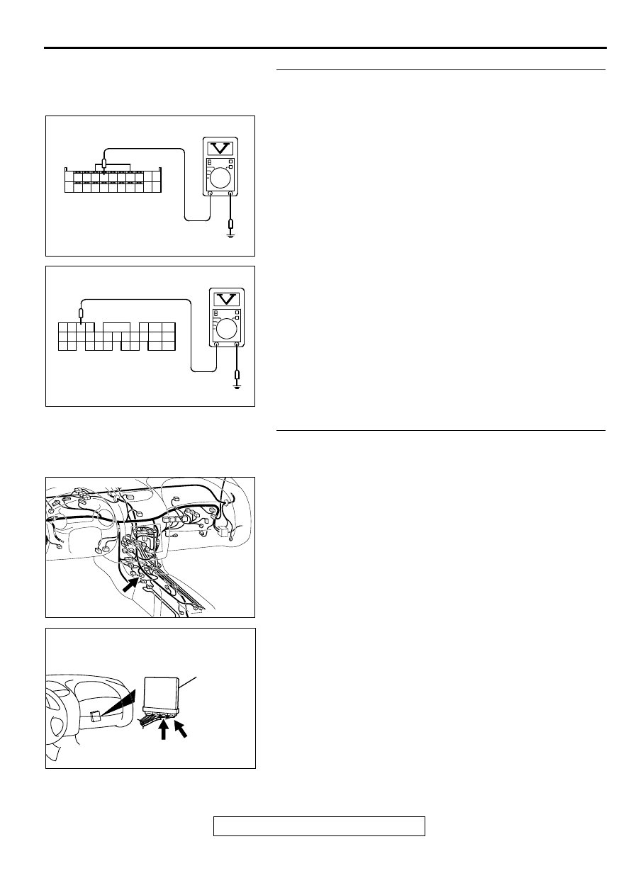
STEP 3. Check the sensor output voltage at ECM
connector C-60 <M/T> or PCM connector C-57 <A/T> by
backprobing.
(1) Do not disconnect the connector C-60 <M/T> or C-57 <A/
T>.
(2) Start the engine and run at idle.
(3) Measure the voltage between terminal 75 <M/T> or 73 <A/
T> and ground by backprobing.
•
Warming up the engine. When the engine is 2,500 r/min,
the output voltage should repeat 0 volt and 0.6 to 1.0
volt alternately.
(4) Turn the ignition switch to the "LOCK" (OFF) position.
Q: Is the voltage normal?
YES : Go to Step 4.
NO : Go to Step 6.
STEP 4. Check connector C-23 at heated oxygen sensor
(rear) and connector C-60 at ECM <M/T> or connector C-57
at PCM <A/T> for damage.
Q: Is the connector in good condition?
YES : Go to Step 5.
NO : Repair or replace it. Refer to GROUP 00E, Harness
Connector Inspection (
AK000292
7172 73 74 75 76 77 78 79 80 81
82 83 84 85 86 87 88 89 90
92
91
AC
<M/T>
C-60 CONNECTOR
HARNESS SIDE VIEW
AK000293
AK000733AB
CONNECTOR:C-23
AK000280
C-60
ECM<M/T>
OR
PCM<A/T>
CONNECTORS:C-60<M/T>,C-57<A/T>
BE
C-57
MULTIPORT FUEL INJECTION (MFI) DIAGNOSIS
TSB Revision
MULTIPORT FUEL INJECTION (MFI) <2.4L ENGINE>
13A-137
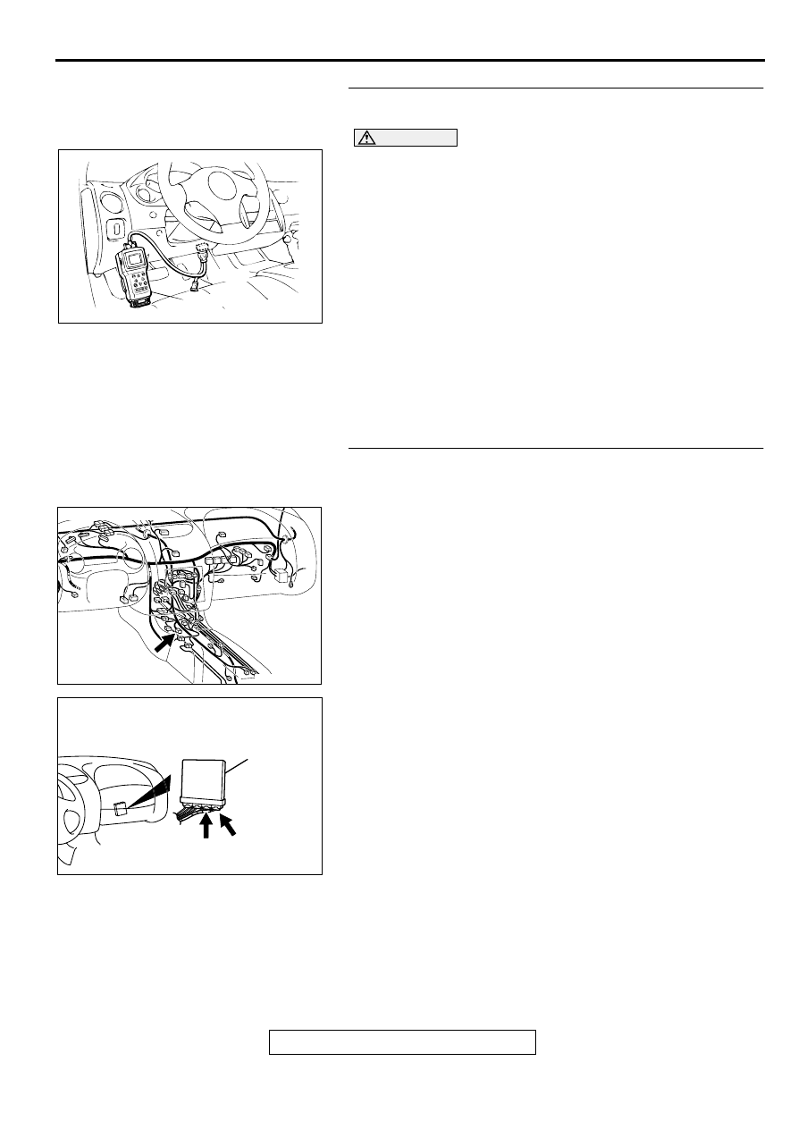
STEP 5. Using scan tool MB991502, check data list item 59:
Heated Oxygen Sensor (rear).
CAUTION
To prevent damage to scan tool MB991502, always turn the
ignition switch to the "LOCK" (OFF) position before
connecting or disconnecting scan tool MB991502.
(1) Connect scan tool MB991502 to the data link connector.
(2) Start the engine and run at idle.
(3) Set scan tool MB991502 to the data reading mode for item
59, Heated Oxygen Sensor (rear).
•
Warming up the engine. When the engine is revved, the
output voltage should repeat 0 volt and 0.6 to 1.0 volt
alternately.
(4) Turn the ignition switch to the "LOCK" (OFF) position.
Q: Is the sensor operating properly?
YES : It can be assumed that this malfunction is intermittent.
Refer to GROUP 00, How to Use Troubleshooting/
Inspection Service Points (
NO : Replace the ECM or PCM. Then go to Step 15.
STEP 6. Check connector C-23 at heated oxygen sensor
(rear) and connector C-60 at ECM <M/T> or connector C-57
at PCM <A/T> for damage.
Q: Is the connector in good condition?
YES : Repair harness wire between heated oxygen sensor
(rear) connector C-23 terminal 3 and ECM connector
C-60 terminal 75 <M/T> or PCM connector C-57
terminal 73 <A/T> because of open circuit or harness
damage. Then go to Step 15.
NO : Repair or replace it. Refer to GROUP 00E, Harness
Connector Inspection (
AKX01177
16 PIN
MB991502
AB
AK000733AB
CONNECTOR:C-23
AK000280
C-60
ECM<M/T>
OR
PCM<A/T>
CONNECTORS:C-60<M/T>,C-57<A/T>
BE
C-57
MULTIPORT FUEL INJECTION (MFI) DIAGNOSIS
TSB Revision
MULTIPORT FUEL INJECTION (MFI) <2.4L ENGINE>
13A-138
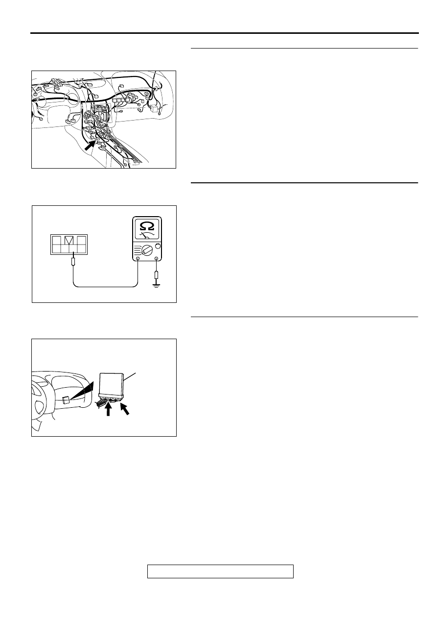
STEP 7. Check connector C-23 at heated oxygen sensor
(rear) for damage.
Q: Is the connector in good condition?
YES : Go to Step 8.
NO : Repair or replace it. Refer to GROUP 00E, Harness
Connector Inspection (
STEP 8. Check the continuity at heated oxygen sensor
(rear) harness side connector C-23.
(1) Disconnect the connector C-23 and measure at the harness
side.
(2) Check for the continuity between terminal 4 and ground.
•
Should be less than 2 ohm.
Q: Is the continuity normal?
YES : Go to Step 11.
NO : Go to Step 9.
STEP 9. Check connector C-60 at ECM <M/T> or connector
C-54 at PCM <A/T> for damage.
Q: Is the connector in good condition?
YES : Go to Step 10.
NO : Repair or replace it. Refer to GROUP 00E, Harness
Connector Inspection (
AK000733AB
CONNECTOR:C-23
AK000321
1
2
3
4
5
6
C-23 HARNESS
SIDE CONNECTOR
AD
AK000280
C-54
C-60
ECM<M/T>
OR
PCM<A/T>
CONNECTORS:C-60<M/T>,C-54<A/T>
BB
Нет комментариевНе стесняйтесь поделиться с нами вашим ценным мнением.
Текст