Mitsubishi Eclipse / Eclipse Spyder (2000-2002). Service and repair manual — part 607
POWER STEERING GEAR BOX ASSEMBLY
TSB Revision
POWER STEERING
37A-23
PO W ER STEERIN G G EA R B O X A SSEM B LY
REMOVAL AND INSTALLATION
M1372003900075
WARNING
Before removing the steering gear box, refer to GROUP 52B. Center the front wheels and
remove the ignition key. Failure to do so may damage the SRS clock spring and render the
SRS system inoperative, risking serious injury.
Pre-removal Operation
•
Power Steering Fluid Draining (Refer to
•
Center Member Removal (Refer to GROUP 32, Engine
Roll Stopper, Centermember
•
Front Exhaust Pipe Removal (2.4L Engine: Refer to
GROUP 15, Exhaust Pipe and Main Muffler
, 3.0L
Engine: Refer to GROUP 15, Exhaust Pipe and Main Muf-
fler
•
Stabilizer Bar Removal <2.4L Engine> (Refer to GROUP
33A, Stabilizer Bar
Post-installation Operation
•
Check the Dust Cover for Cracks or Damage by Pushing
it with Finger.
•
Stabilizer Bar Installation <2.4L Engine> (Refer to
GROUP 33A, Stabilizer Bar
.)
•
Front Exhaust Pipe Installation (2.4L Engine: Refer to
GROUP 15, Exhaust Pipe and Main Muffler
, 3.0L
Engine: Refer to GROUP 15, Exhaust Pipe and Main Muf-
fler
•
Center Member Installation (Refer to GROUP 32, Engine
Roll Stopper, Centermember
.)
•
Power Steering Fluid Supplying (Refer to
.)
•
Power Steering Fluid Line Bleeding (Refer to
•
Checking Steering Wheel Position with Wheels Straight
Ahead.
•
Front Wheel Alignment Adjustment (Refer to GROUP
33A, On-vehicle Service
−
Front Wheel Alignment Check
and Adjustment
AC000994 AD
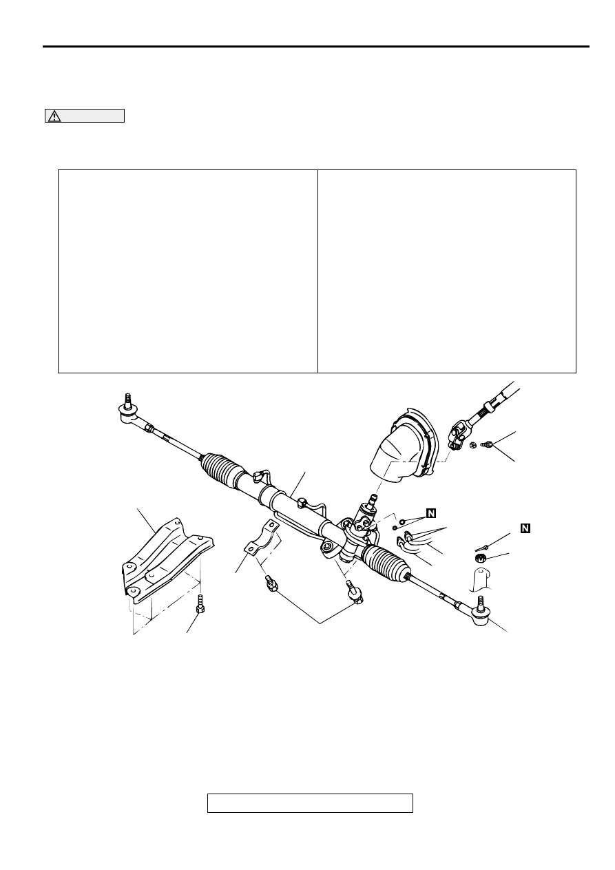
1
8
7
6
5
4
3
2
18 ± 2 N·m
13 ± 1 ft-lb
15 ± 3 N·m
11 ± 2 ft-lb
29 ± 4 N·m
21 ± 4 ft-lb
74 ± 4 N·m
55 ± 3 ft-lb
69 ± 9 N·m
51 ± 7 ft-lb
<2.4L ENGINE>
POWER STEERING GEAR BOX ASSEMBLY
TSB Revision
POWER STEERING
37A-24
Required Special Tools:
•
MB990228 or MB991006: Preload Socket
•
MB991113 or MB990635: Steering Linkage Puller
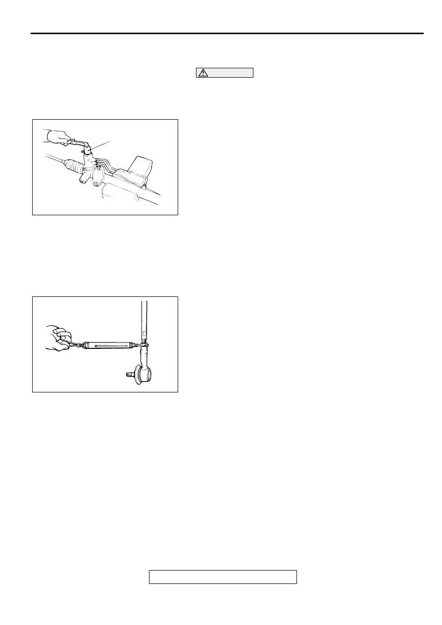
REMOVAL SERVICE POINTS
<<A>> TIE ROD END DISCONNECTION
CAUTION
•
Loosen the nut from the ball joint instead of removing
it.
•
Hang special tool MB991113 or MB990635 with ropes to
prevent it from falling.
Use special tool MB991113 or MB990635 to disconnect the ball
joint.
<<B>> GEAR BOX ASSEMBLY REMOVAL
CAUTION
Be sure not to damage the bellows and the tie rod end dust
cover when removing the gear box assembly.
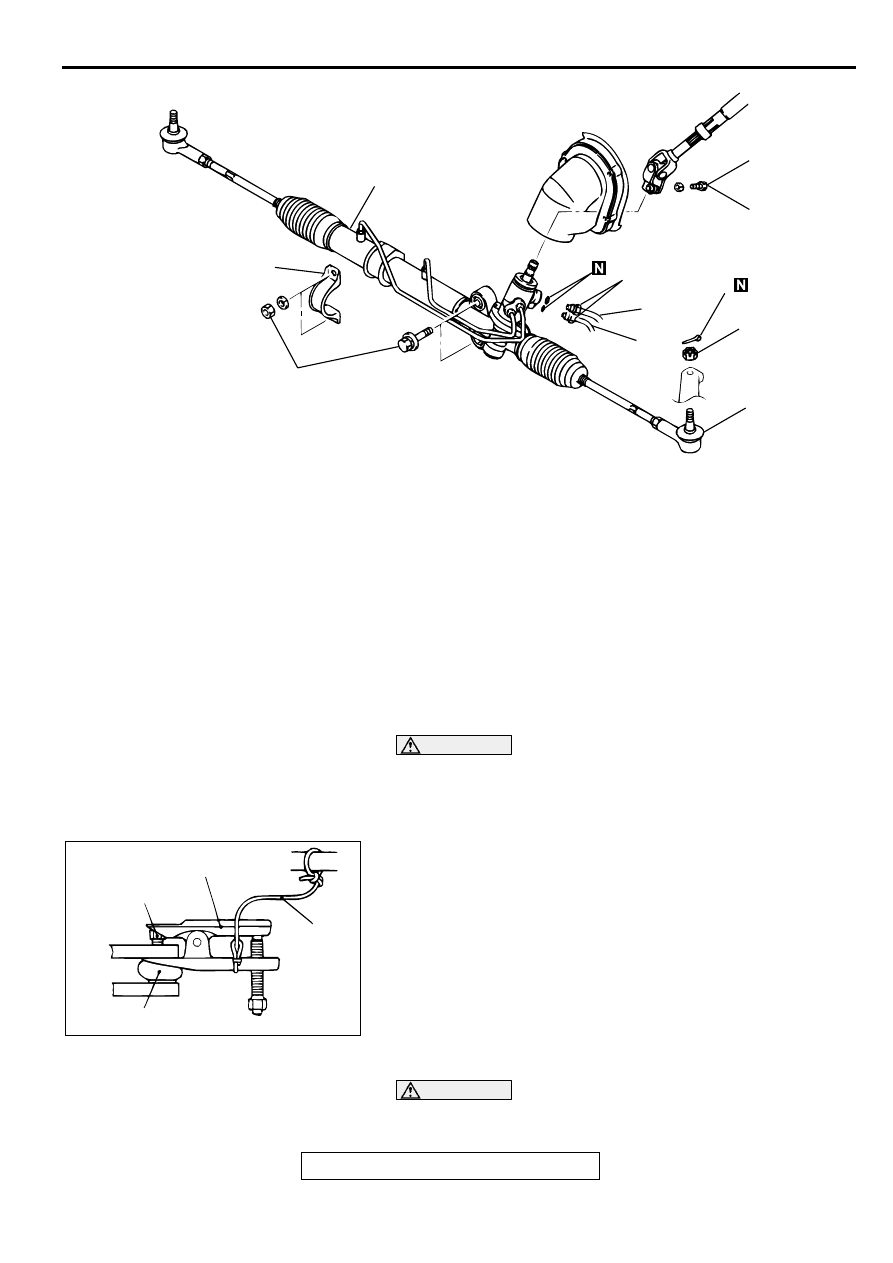
AC003541AC
1
8
7
6
5
4
3
18 ± 2 N·m
13 ± 1 ft-lb
15 ± 3 N·m
11 ± 2 ft-lb
29 ± 4 N·m
21 ± 4 ft-lb
69 ± 9 N·m
51 ± 7 ft-lb
<3.0L ENGINE>
REMOVAL STEPS
1.
STEERING SHAFT ASSEMBLY AND
GEAR BOX CONNECTING BOLT
2.
STAY <2.4L ENGINE>
3.
COTTER PIN
<<A>>
4.
TIE ROD END AND KNUCKLE
CONNECTION
5.
RETURN HOSE CONNECTION
6.
PRESSURE TUBE CONNECTION
7.
CYLINDER CLAMP
<<B>>
8.
GEAR BOX ASSEMBLY
REMOVAL STEPS (Continued)
ACX01123AB
NUT
BALL JOINT
CORD
MB991113 OR MB990635
POWER STEERING GEAR BOX ASSEMBLY
TSB Revision
POWER STEERING
37A-25
INSPECTION
M1372003200032
GEAR BOX TOTAL PINION TORQUE CHECK
CAUTION
When holding the steering gear box assembly in a vice,
secure its mounting positions. If it is secured in any other
places, the gear housing may become deformed or
damaged.
Using special tool MB990228 or MB991006, rotate the pinion
gear at the rate of one rotation in approximately 4 to 6 seconds
to check the total pinion torque.
Standard value: 0.8
−
1.9 N
⋅
m (6.9
−
16.5 in-lb)
[Change in torque: 0.7 N
⋅
m (6.1 in-lb) or less]
NOTE: When measuring, remove the bellows from the rack
housing. Measure the pinion torque through the whole stroke of
the rack.
If the measured value is not within the standard range, first
adjust the rack support cover, and then check the total pinion
torque again.
If the total pinion torque cannot be adjusted to within the
standard range by adjusting the rack support cover, check the
rack support cover, rack support spring, rack support and
replace any parts if necessary.
TIE ROD SWING RESISTANCE CHECK
1. Give 10 hard swings to the tie rod.
2. Measure the tie rod swing resistance with a spring scale.
Standard value: 4.0
−
18.6 N (17.8
−
82.7 lb) [1.0
−
4.9
N
⋅
m (8.7
−
43.4 in-lb)]
3. If the measured value exceeds the standard value, replace
tie rod.
4. If the measured value is below the standard value, the tie
rod can be re-used if it swings smoothly without excessive
play.
TIE ROD END BALL JOINT DUST COVER CHECK
1. Check the dust cover for cracks or damage by pushing it
with your finger.
2. If the dust cover is cracked or damaged, replace the tie rod
end. (Refer to
NOTE: Cracks or damage of the dust cover may damage
the ball joint. If it is damaged during service work, replace
the dust cover. (Refer to
AC000996 AB
MB990228
OR
MB991006
AC000997
POWER STEERING GEAR BOX ASSEMBLY
TSB Revision
POWER STEERING
37A-26
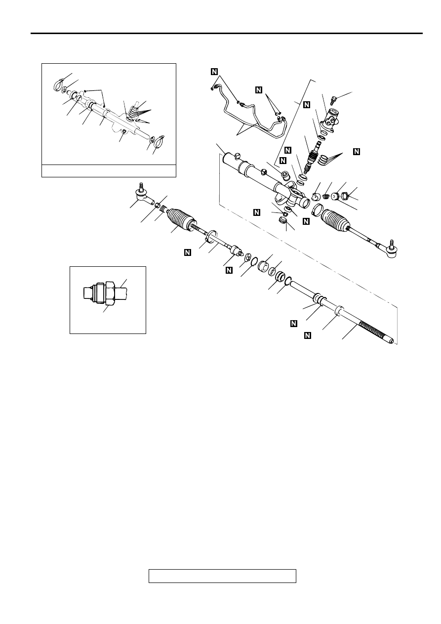
DISASSEMBLY AND ASSEMBLY
M1372004100072
AC000999
1
13 12 11
10
9
8
7
6
5
4
3
2
14
15
18
17
16
19
20
2
21
22
23
24
25
26
27
28
29
30
31
32
33
34
35
1
9
6
2
15
19
2
21
27
28
29
30
33
9
6
17
52 ± 2 N·m
38 ± 2 ft-lb
88 ± 10 N·m
65 ± 7 ft-lb
13 ± 3 N·m
113 ± 26 in-lb
59 ± 10 N·m
44 ± 7 ft-lb
13 ± 2 N·m*
109 ± 21 in-lb*
59 ± 10 N·m
44 ± 7 ft-lb
25 ± 4 N·m
18 ± 4 ft-lb
STEERING GEAR SEAL KIT
FLARE NUT
NOTE
*: Return the rack support cover
–
10˚.
AB
19 ± 3 N·m
14 ± 2 ft-lb
DISASSEMBLY STEPS
1.
FEED TUBE
2.
O-RING
>>O<<
3.
TIE ROD END JAM NUT
>>O<<
4.
TIE ROD END
5.
BELLOWS CLIP
>>N<<
6.
BELLOWS BAND
7.
BELLOWS
<<A>> >>M<<
8.
TIE ROD
<<A>> >>M<<
9.
TAB WASHER
>>L<<
•
TOTAL PINION TORQUE
ADJUSTMENT
>>K<<
10.
JAM NUT
<<B>> >>K<<
11.
RACK SUPPORT COVER
12.
RACK SUPPORT SPRING
13.
RACK SUPPORT
>>J<<
14.
END PLUG
15.
JAM NUT
16.
VALVE HOUSING ASSEMBLY
<<C>> >>I<<
17.
OIL SEAL
<<C>>
18.
PINION AND VALVE ASSEMBLY
<<D>> >>H<<
19.
SEAL RING
<<E>> >>G<<
20.
BALL BEARING
<<E>> >>G<<
21.
OIL SEAL
22.
VALVE HOUSING
<<F>> >>F<<
23.
CIRCLIP
24.
RACK STOPPER
>>E<<
25.
RACK BUSHING
<<G>> >>D<<
26.
RACK
>>C<<
27.
O-RING
<<H>> >>C<<
28.
OIL SEAL
29.
SEAL RING
30.
O-RING
<<I>>
>>B<<
31.
BALL BEARING
<<J>> >>B<<
32.
NEEDLE ROLLER BEARING
<<K>> >>A<<
33.
OIL SEAL
34.
BUSHING
35.
RACK HOUSING
DISASSEMBLY STEPS (Continued)
Нет комментариевНе стесняйтесь поделиться с нами вашим ценным мнением.
Текст