Mitsubishi Eclipse / Eclipse Spyder (2000-2002). Service and repair manual — part 606
ON-VEHICLE SERVICE
TSB Revision
POWER STEERING
37A-19
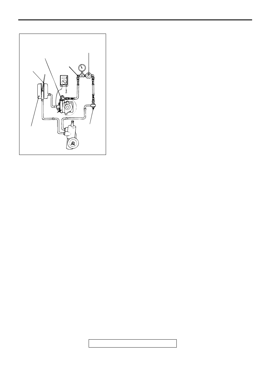
POWER STEERING PRESSURE SWITCH CHECK
M1372007200078
Required Special Tools:
•
MB990662: Pressure Gauge
•
MB991548: Power Steering Oil Pressure Gauge Adapter
(Pump Side)
•
MB991549: Power Steering Oil Pressure Gauge Adapter
(Hose Side)
1. Disconnect the pressure hose from the oil pump, and then
connect special tools MB991548, MB990662 and
MB991549.
2. Bleed air, and then turn the steering wheel several times
while the vehicle is not moving so that the temperature of
the fluid rises to approximately 50
−
60
°
C (122
−
140
°
F).
3. The engine should be idling.
4. Disconnect the connector for the oil pressure switch, and
place an ohmmeter.
5. Gradually close the shut-off valve of the pressure gauge and
increase the hydraulic pressure, then check whether or not
the hydraulic pressure that activates the switch is the
standard value.
Standard value: 1.8
−
2.4 MPa (261
−
348 psi)
6. Gradually open the shut-off valve and reduce the hydraulic
pressure; then check whether or not the hydraulic pressure
that deactivates the switch is the standard value.
Standard value: 0.8
−
2.4 MPa (116
−
348 psi)
7. Remove special tools MB991548, MB990662 and
MB991549, and then tighten the pressure hose to the
specified torque.
Tightening torque: 57
±
7 N
⋅
m (42
±
5 ft-lb)
8. Bleed the system.
BALL JOINT DUST COVER CHECK
M1372008600079
1. Press the dust cover with your finger to check whether the
dust cover is cracked or damaged.
2. If the dust cover is cracked or damaged, replace the tie rod
end.
NOTE: If the dust cover is cracked or damaged, the ball joint
could be damaged.
ACX01134 AB
THERMO-
METER
ADAPTER
(MB991548)
RESERVOIR
OIL
PUMP
ADAPTER
(MB991549)
SHUT-OFF
VALVE
PRESSURE
GAUGE
(MB990662)
STEERING WHEEL AND SHAFT ASSEMBLY
TSB Revision
POWER STEERING
37A-20
STEER IN G W H EEL A N D SH AFT A SSEM BLY
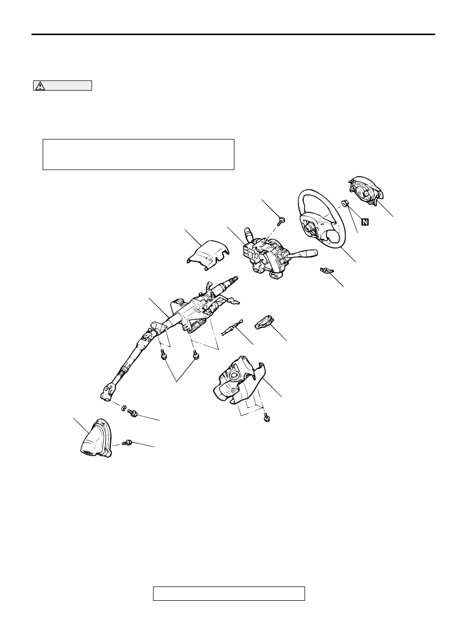
REMOVAL AND INSTALLATION
M1372002600071
WARNING
•
Before removing the air bag module, refer to GROUP 52B, Service Precautions and Air
Bag Module and Clock Spring
•
When removing and installing the steering wheel, do not let it bump against the air bag
module.
Required Special Tool:
•
MB990803:Steering Wheel Puller
Post-installation Operation
•
Checking Steering Wheel Position with Wheels Straight
Ahead
AC000990
1
10
9
8
7
6
5
4
3
2
25 ± 4 N·m
18 ± 4 ft-lb
12 ± 2 N·m
100 ± 22 in-lb
18 ± 2 N·m
13 ± 1 ft-lb
4.9 ± 1.0 N·m
44 ± 8 in-lb
AC
41 ± 8 N·m
31 ± 5 ft-lb
REMOVAL STEPS
1.
AIR BAG MODULE (REFER TO
GROUP 52B, AIR BAG MODULE
AND CLOCK SPRING
<<A>>
2.
STEERING WHEEL
3.
COVER
•
INSTRUMENT PANEL UNDER
COVER (REFER TO GROUP 52A,
INSTRUMENT PANEL
.)
4.
LOWER COLUMN COVER
5.
UPPER COLUMN COVER
6.
CLOCK SPRING AND COLUMN
SWITCH ASSEMBLY (REFER TO
GROUP 52B, AIR BAG MODULE
AND CLOCK SPRING
.)
7.
COVER <A/T>
8.
KEY INTERLOCK CABLE <A/T>
9.
STEERING SHAFT ASSEMBLY
10. STEERING COVER ASSEMBLY
REMOVAL STEPS (Continued)
STEERING WHEEL AND SHAFT ASSEMBLY
TSB Revision
POWER STEERING
37A-21
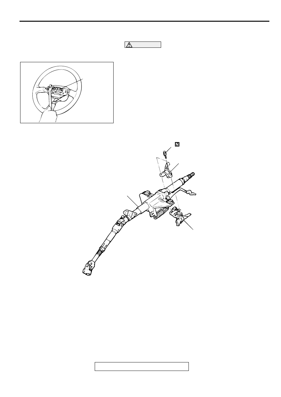
REMOVAL SERVICE POINT
<<A>> STEERING WHEEL REMOVAL
CAUTION
Do not hammer on the steering wheel to remove it; doing
so will damage the collapsible mechanism.
Use special tool MB990803 to remove the steering wheel.
DISASSEMBLY AND ASSEMBLY
M1372002800075
AC000991AB
MB990803
AC000992
1
4
3
AB
2
DISASSEMBLY STEPS
>>A<<
1.
SPECIAL BOLT
<<A>> >>A<<
2.
STEERING LOCK BRACKET
<<A>> >>A<<
3.
STEERING LOCK CYLINDER
4.
STEERING COLUMN ASSEMBLY
DISASSEMBLY STEPS (Continued)
STEERING WHEEL AND SHAFT ASSEMBLY
TSB Revision
POWER STEERING
37A-22
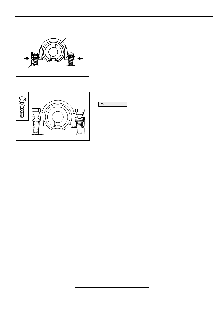
DISASSEMBLY SERVICE POINT
<<A>> STEERING LOCK BRACKET/STEERING LOCK
CYLINDER REMOVAL
If it is necessary to remove the steering lock cylinder, use a
hacksaw to cut the special bolts at the steering lock bracket
side.
ASSEMBLY SERVICE POINT
>>A<< STEERING LOCK CYLINDER/STEERING LOCK
BRACKET/SPECIAL BOLT INSTALLATION
CAUTION
The steering lock bracket and bolts must be replaced with
new ones when the steering lock is installed.
1. When installing the steering lock cylinder and steering lock
bracket to the column tube, temporarily install the steering
lock in alignment with the column boss.
2. After checking that the lock works properly, tighten the
special bolts until the head twists off.
AC000993 AB
STEERING LOCK CYLINDER
STEERING LOCK BRACKET
ACX01139 AB
Нет комментариевНе стесняйтесь поделиться с нами вашим ценным мнением.
Текст