Mitsubishi Eclipse / Eclipse Spyder (2000-2002). Service and repair manual — part 375
AUTO-CRUISE CONTROL
TSB Revision
ENGINE AND EMISSION CONTROL
17-19
DTC14 : Stoplight Switch System
AC005110AB
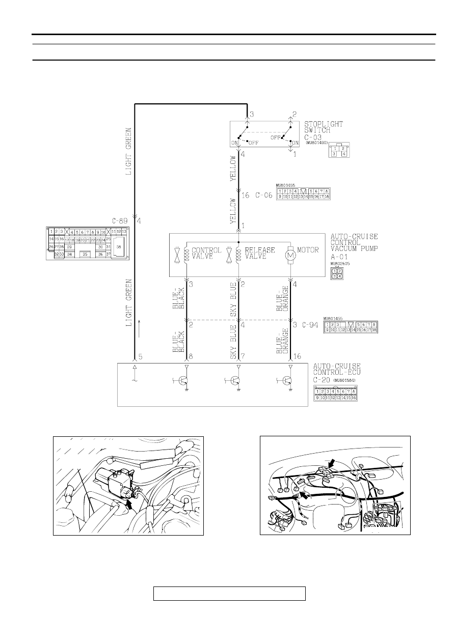
Stoplight Switch System Circuit
AC001449
CONNECTOR: A-01
RESERVE
TANK
AB
AC003552 AJ
CONNECTORS: C-03, C-06
C-06
C-03
AUTO-CRUISE CONTROL
TSB Revision
ENGINE AND EMISSION CONTROL
17-20
CIRCUIT OPERATION
This circuit supplies the power to the vacuum pump.
The battery positive voltage is supplied to the auto-
cruise control vacuum pump by turning on the
transistor at terminal number 16 of the auto-cruise
control-ECU.
The conditions for turning on the transistor at
terminal number 16 of the auto-cruise control-ECU
are as follows.
•
Ignition switch "ON"
•
Auto-cruise control main switch "ON"
•
Stoplight switch ON
DTC SET CONDITIONS
None of the drive signals from release valve, control
valve and motor of the auto-cruise vacuum pump are
input to the auto-cruise control-ECU.
TROUBLESHOOTING HINTS
The most likely causes for this code to be set are:
•
Malfunction of the stoplight switch
•
Malfunction of the auto-cruise vacuum pump
•
Damaged harness or connector.
•
Malfunction of the auto-cruise control-ECU
DIAGNOSIS
Required Special Tool:
•
MB991223: Harness Set
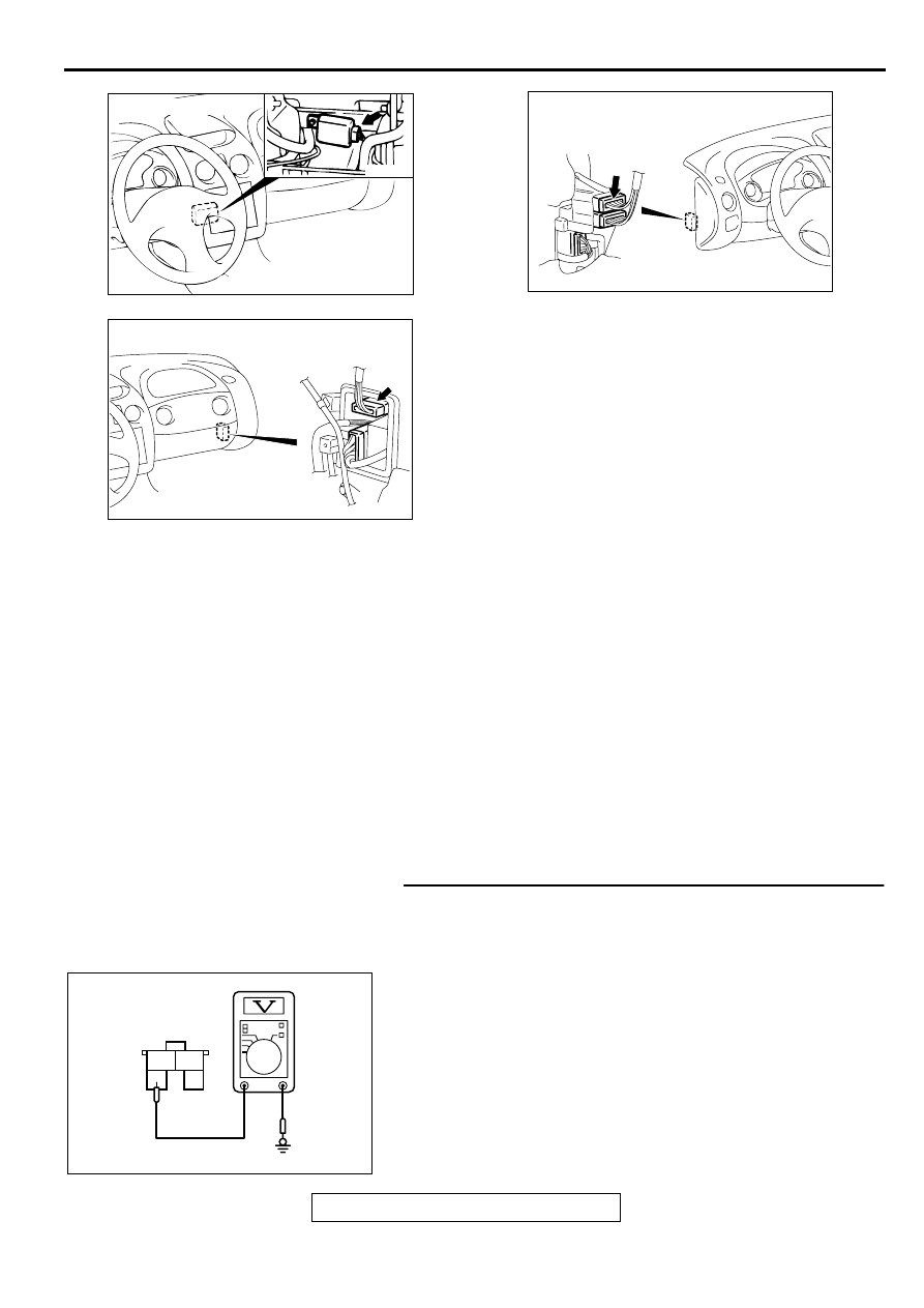
STEP 1. Check the output circuit voltage at stoplight
switch connector C-03 by backprobing.
(1) Do not disconnect stoplight switch connector C-03.
(2) Turn the ignition switch to "ON" position.
(3) Measure the voltage between terminal 3 and ground by
backprobing.
(4) Turn the ignition switch to "LOCK" (OFF) position.
Q: Is the voltage approximately battery positive voltage?
YES : Go to Step 3.
NO : Go to Step 2.
AC001451
CONNECTOR: C-20
AB
AC001991AM
CONNECTOR: C-89
CONNECTOR
BLOCK (LH)
AC001992
CONNECTOR: C-94
AF
CONNECTOR
BLOCK (RH)
1
3
4
2
ACX01910
C-03 CONNECTOR
HARNESS SIDE VIEW
AC
AUTO-CRUISE CONTROL
TSB Revision
ENGINE AND EMISSION CONTROL
17-21
STEP 2. Check stoplight switch connector C-03.
Q: Is the connector damaged?
YES : Repair or replace connector.
Refer to GROUP 00E, Harness Connector Inspection
.
Then check that diagnostic trouble code 14 is not
output.
NO : Go to Step 13.
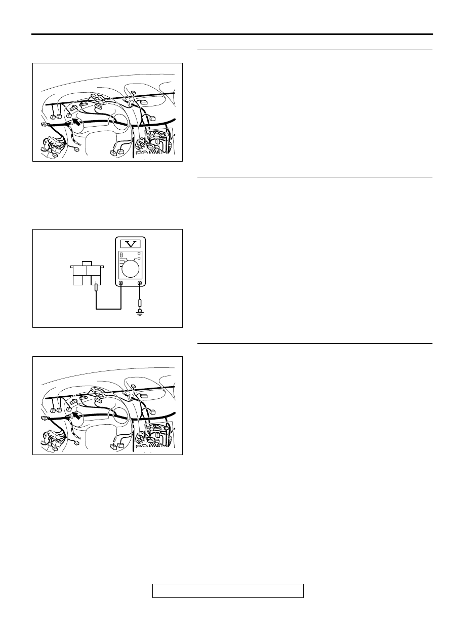
STEP 3. Check the output circuit voltage at stoplight
switch connector C-03 by backprobing.
(1) Do not disconnect stoplight switch connector C-03.
(2) Turn the ignition switch to "ON" position and the auto-cruise
control main switch to "ON" position.
(3) Measure the voltage between terminal 4 and ground by
backprobing.
(4) Turn the ignition switch to "LOCK" (OFF) position.
Q: Is the voltage approximately battery positive voltage?
YES : Go to Step 6.
NO : Go to Step 4.
STEP 4. Check stoplight switch connector C-03.
Q: Is the connector damaged?
YES : Repair or replace connector.
Refer to GROUP 00E, Harness Connector Inspection
.
Then check that diagnostic trouble code 14 is not
output.
NO : Go to Step 5.
AC003552 AK
CONNECTOR: C-03
1
3
4
2
ACX01911AC
C-03 CONNECTOR
HARNESS SIDE VIEW
AC003552 AK
CONNECTOR: C-03
AUTO-CRUISE CONTROL
TSB Revision
ENGINE AND EMISSION CONTROL
17-22
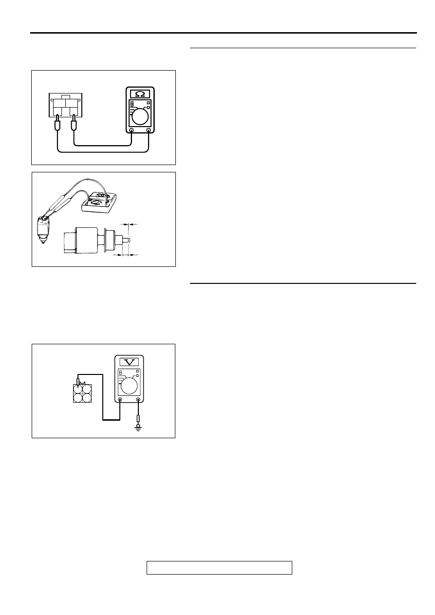
STEP 5. Check the stoplight switch.
(1) Disconnect stoplight switch connector C-03.
(2) Connect an ohmmeter to the stoplight switch between
terminals 3 and 4, and check whether there is continuity
when the plunger of the stoplight switch is pushed in and an
open circuit when it is released.
(3) The stoplight switch is in good condition if the circuit is open
when the plunger is pushed in to a depth of within 4 mm
(0.2 inch) from the outer case edge surface, and if there is
continuity when it is released.
Q: Is the circuit is open?
YES : Replace the stoplight switch.
Refer to GROUP 35A, Brake Pedal
Then check that a diagnostic trouble code 14 is not
output.
NO : Check that diagnostic trouble code 14 is not output.
If diagnostic trouble code 14 is output, replace the
auto-cruise control-ECU. (Refer to
.)
Then check that diagnostic trouble code 14 is not
output.
STEP 6. Check the output circuit voltage at auto-cruise
control vacuum pump connector A-01 by backprobing.
(1) Do not disconnect auto-cruise control vacuum pump
connector A-01.
(2) Turn the ignition switch to "ON" position and the auto-cruise
control main switch to "ON" position.
(3) Measure the voltage between terminal 1 and ground by
backprobing.
(4) Turn the ignition switch to "LOCK" (OFF) position.
Q: Is the voltage approximately battery positive voltage?
YES : Go to Step 8.
NO : Go to Step 7.
1
2
3
4
ACX01917
STOPLIGHT SWITCH
CONNECTOR: C-03
AC
AC001463
CONTINUITY
NO
CONTINUITY
4 mm (0.2 in)
AB
1
2
3
4
ACX01908AC
A-01 CONNECTOR
HARNESS SIDE VIEW
Нет комментариевНе стесняйтесь поделиться с нами вашим ценным мнением.
Текст