Mitsubishi Eclipse / Eclipse Spyder (2000-2002). Service and repair manual — part 123
MULTIPORT FUEL INJECTION (MFI) DIAGNOSIS
TSB Revision
MULTIPORT FUEL INJECTION (MFI) <2.4L ENGINE>
13A-191
DTC P0340: Camshaft Position Sensor Circuit Malfunction
AK000664
2
1
3
3 4
1 2
RED
-
WHITE
RED
-
WHITE
RED
-
WHITE
RED
BL
ACK
BL
ACK
BL
UE-
YELL
OW
BATTERY
MFI RELAY
A-21X
CAMSHAFT
POSITION
SENSOR
B-09
MU802337
C-54<A/T>
(MU803781)
C-60<M/T>
(MU803772)
88<M/T>
56<A/T>
5V
1
1
2
2
3
3
4
ENGINE CONTROL
MODULE(ECM)<M/T>
OR
POWERTRAIN CONTROL
MODULE(PCM)<A/T>
42 43
48 49 50 51 52 53 54 55 56 57
46
45
44
58 59
60 61 62 63
64 65 66
47
41
82
78
81
80
89 90 91 92
79
87
71
74
73
72
76
75
77
85
88
83 84
86
JOINT
GROUND
POINT
MULTIPORT FUEL INJECTION (MFI) DIAGNOSIS
TSB Revision
MULTIPORT FUEL INJECTION (MFI) <2.4L ENGINE>
13A-192
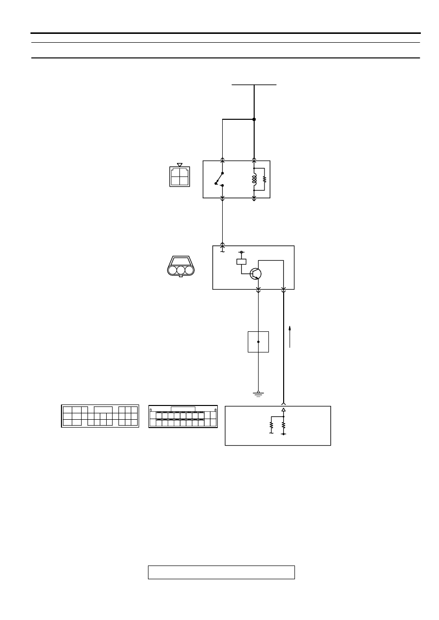
CIRCUIT OPERATION
•
The camshaft position sensor power is supplied
from the MFI relay (terminal 1). Ground is
provided through terminal 1 to chassis ground.
•
A 5-volt voltage is applied on the camshaft
position sensor output terminal (terminal 2) from
the ECM (terminal 88) <M/T> or PCM (terminal
56) <A/T>. The camshaft position sensor
generates a pulse signal when the output
terminal is opened and grounded.
TECHNICAL DESCRIPTION
•
The camshaft position sensor functions to detect
the top dead center position of the number 1
cylinder and to convert that data to pulse signals
that are input to the ECM <M/T> or PCM <A/T>.
•
When the engine is running, the camshaft
position sensor outputs a pulse signal.
•
The ECM <M/T> or PCM <A/T> checks whether
pulse signal is input while the engine is cranking.
DTC SET CONDITIONS
Check Conditions
•
Engine speed is higher than 50 r/min.
Judgment Criteria
•
Camshaft position sensor output voltage has not
changed (no pulse signal is input) for 2 seconds.
Check Conditions
•
Engine speed is higher than 50 r/min.
Judgment Criteria
•
Normal signal pattern has not been input for
cylinder identification from the crankshaft position
sensor signal and camshaft position sensor
signal for 2 seconds.
TROUBLESHOOTING HINTS (The most likely
causes for this code to be set are:)
•
Camshaft position sensor failed.
•
Open or shorted camshaft position sensor circuit,
or loose connector.
•
ECM failed. <M/T>
•
PCM failed. <A/T>
AK000276AB
AK000276
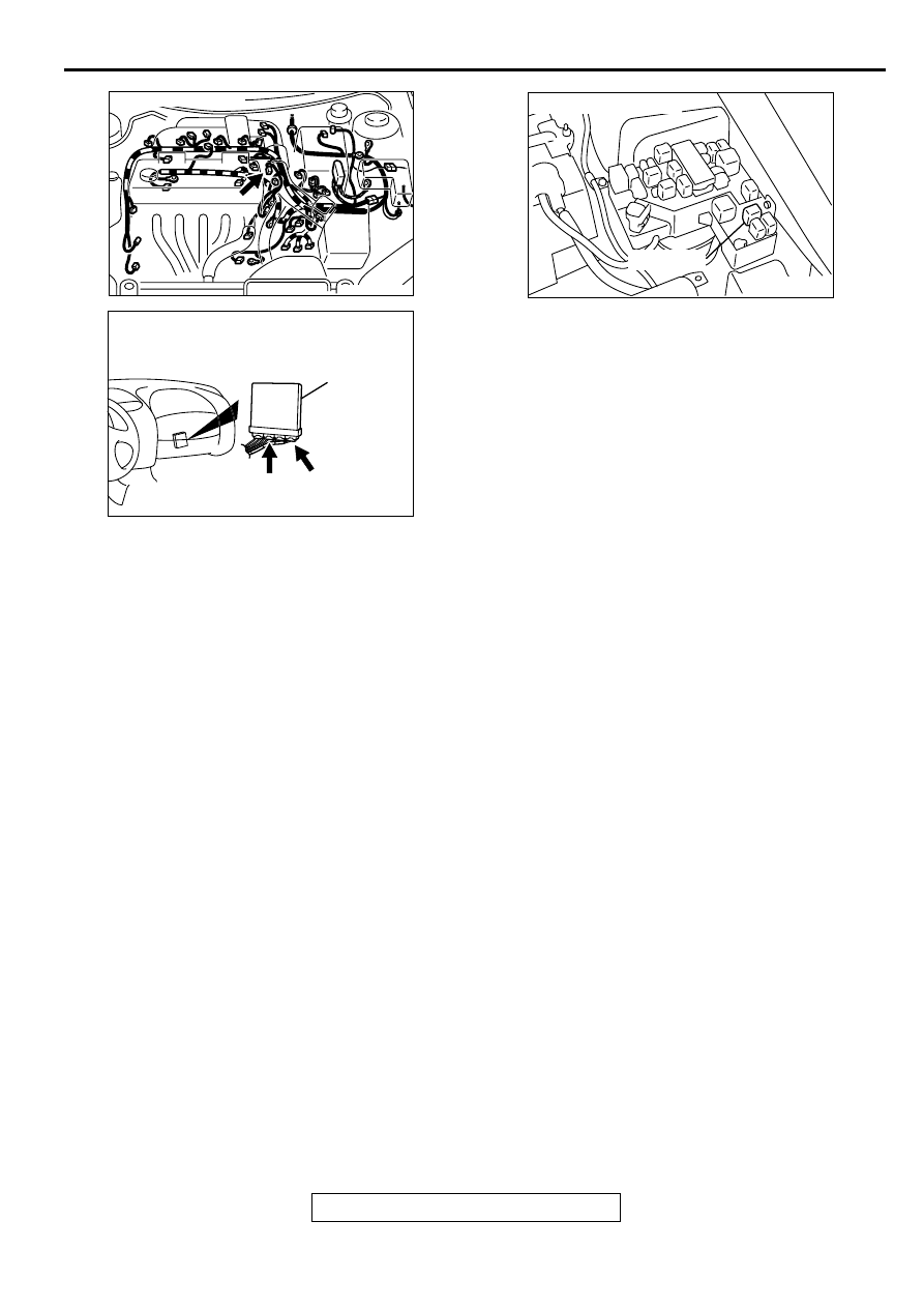
CONNECTOR : B-09
AK000280
C-54
C-60
ECM<M/T>
OR
PCM<A/T>
CONNECTORS:C-60<M/T>,C-54<A/T>
BB
AK000226
AK000226AB
CONNECTOR : A-21X
MFI RELAY
MULTIPORT FUEL INJECTION (MFI) DIAGNOSIS
TSB Revision
MULTIPORT FUEL INJECTION (MFI) <2.4L ENGINE>
13A-193
DIAGNOSIS
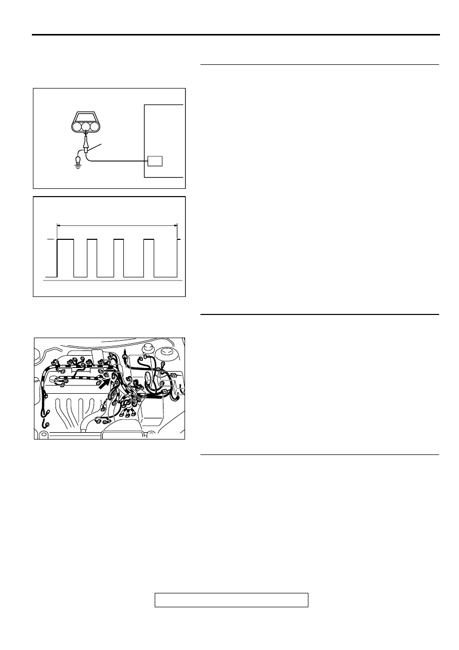
STEP 1. Using the oscilloscope, check the camshaft
position sensor.
(1) Disconnect the camshaft position sensor connector B-09,
and connect test harness special tool (MB991348) in
between. (All terminals should be connected.)
(2) Connect the oscilloscope probe to the camshaft position
sensor side connector terminal 2.
NOTE: When measuring with the ECM or PCM side
connector, connect an oscilloscope probe to terminal 88
<M/T> or terminal 56 <A/T>.
(3) Start the engine and run at idle.
(4) Check the waveform.
•
The waveform should show a pattern similar to the
illustration.
(5) Turn the ignition switch to the "LOCK" (OFF) position.
Q: Is the waveform normal?
YES : Go to Step 2.
NO : Go to Step 4.
STEP 2. Check connector B-09 at camshaft position
sensor for damage.
Q: Is the connector in good condition?
YES : Go to Step 3.
NO : Repair or replace it. Refer to GROUP 00E, Harness
Connector Inspection (
STEP 3. Check the trouble symptoms.
(1) Carry out a test drive with the drive cycle pattern. Refer to,
Procedure 6
−
Other Monitor (
).
(2) Check the diagnostic trouble code (DTC).
Q: Is the DTC P0340 is output?
YES : Replace the ECM or PCM. Then go to Step 18.
NO : It can be assumed that this malfunction is intermittent.
Refer to GROUP 00, How to Use Troubleshooting/
Inspection Service Points (
AKX01419 AB
CAMSHAFT POSITION
SENSOR CONNECTOR
1 2 3
OSCILLOSCOPE
OSCILLO-
SCOPE
PROBE
AKX01420AB
2 ENGINE REVOLUTIONS
NORMAL WAVEFORM
5V
AK000276AB
AK000276
CONNECTOR : B-09
MULTIPORT FUEL INJECTION (MFI) DIAGNOSIS
TSB Revision
MULTIPORT FUEL INJECTION (MFI) <2.4L ENGINE>
13A-194
STEP 4. Check connector B-09 at camshaft position
sensor for damage.
Q: Is the connector in good condition?
YES : Go to Step 5.
NO : Repair or replace it. Refer to GROUP 00E, Harness
Connector Inspection (
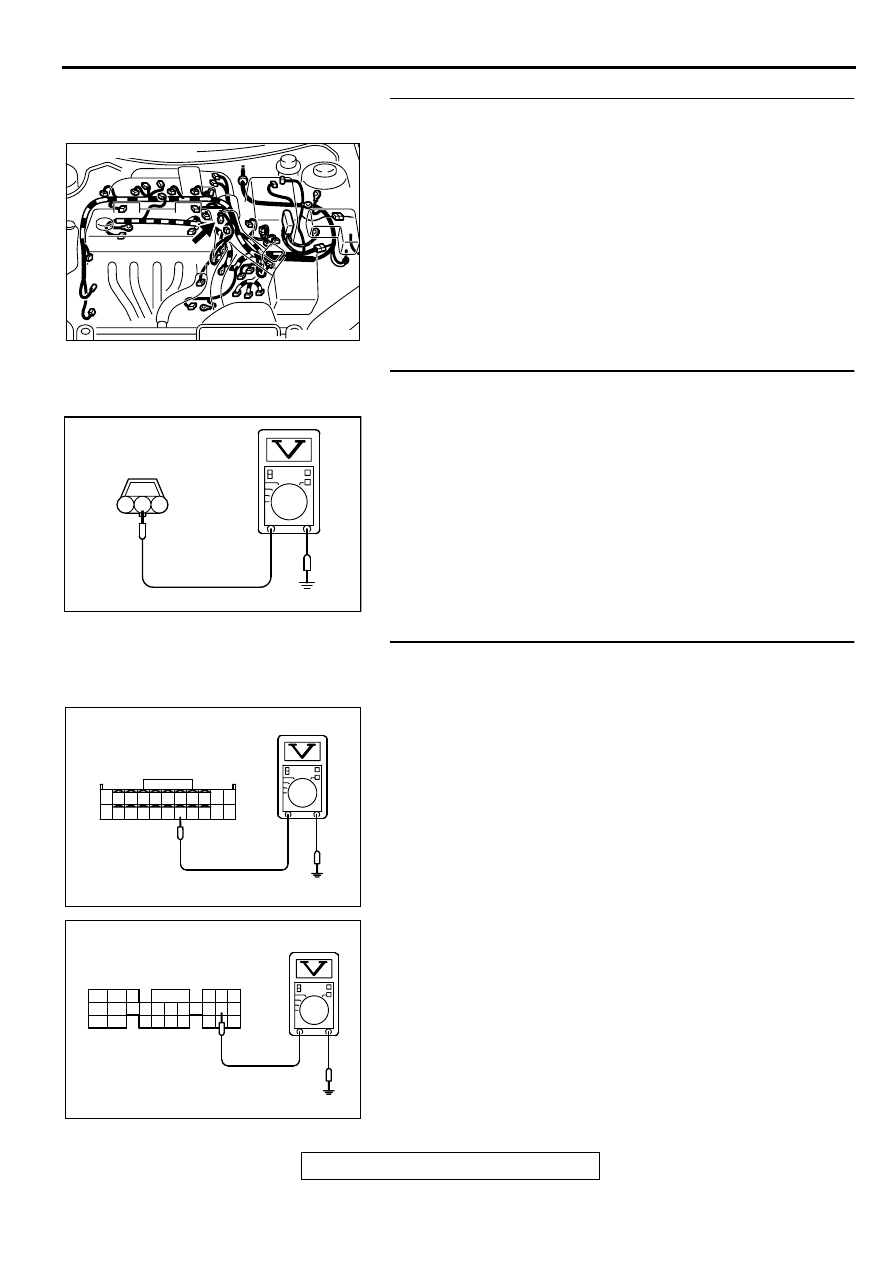
STEP 5. Check the sensor supply voltage at camshaft
position sensor connector B-09.
(1) Disconnect the connector B-09 and measure at the harness
side.
(2) Turn the ignition switch to the "ON" position.
(3) Measure the voltage between terminal 2 and ground.
•
Voltage should be between 4.8 and 5.2 volts
(4) Turn the ignition switch to the "LOCK" (OFF) position.
Q: Is the voltage normal?
YES : Go to Step 10.
NO : Go to Step 6.
STEP 6. Check the sensor supply voltage at ECM
connector C-60 <M/T> or PCM connector C-54 <A/T> by
backprobing
(1) Do not disconnect the ECM connector C-60 <M/T> or PCM
connector C-54 <A/T>.
(2) Disconnect the camshaft position sensor connector B-09.
(3) Turn the ignition switch to the "ON" position.
(4) Measure the voltage between terminal 88 <M/T> or 56 <A/
T> and ground by backprobing.
•
Voltage should be between 4.8 and 5.2 volts.
(5) Turn the ignition switch to the "LOCK" (OFF) position.
Q: Is the voltage normal?
YES : Go to Step 7.
NO : Go to Step 8.
AK000276AB
AK000276
CONNECTOR : B-09
AKX01421AC
B-09 HARNESS
SIDE CONNECTOR
3 2 1
AK000317
7172 73 74 75 76 77 78 79 80 81
82 83 84 85 86 87 88 89 90
92
91
AC
<M/T>
C-60 CONNECTOR
HARNESS SIDE VIEW
AK000318
C-54 CONNECTOR
HARNESS SIDE VIEW
46
57
66
45
56
44
55
43
49
54
64
42
48
59
41
47
58
53
63
52
62
51
61
50
60
AD
<A/T>
Нет комментариевНе стесняйтесь поделиться с нами вашим ценным мнением.
Текст