Mitsubishi Eclipse / Eclipse Spyder (2000-2002). Service and repair manual — part 121
MULTIPORT FUEL INJECTION (MFI) DIAGNOSIS
TSB Revision
MULTIPORT FUEL INJECTION (MFI) <2.4L ENGINE>
13A-183
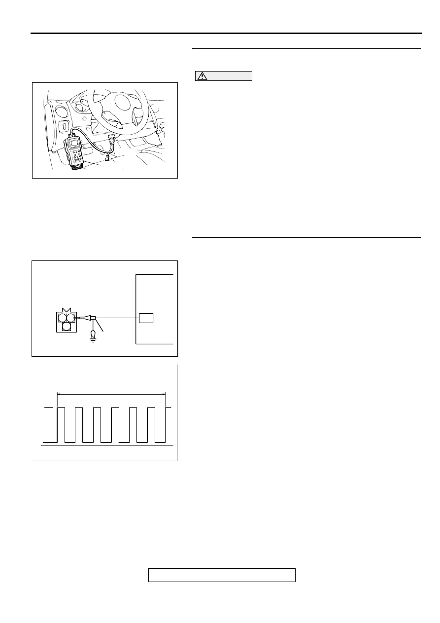
STEP 1. Using scan tool MB991502, check data list item 22:
Crankshaft Position Sensor.
CAUTION
To prevent damage to scan tool MB991502, always turn the
ignition switch to the "LOCK" (OFF) position before
connecting or disconnecting scan tool MB991502.
(1) Connect scan tool MB991502 to the data link connector.
(2) Start the engine and run at idle.
(3) Set scan tool MB991502 to the data reading mode for item
22, Crankshaft Position Sensor.
•
The tachometer and engine speed indicated on the scan
tool should much.
(4) Turn the ignition switch to the "LOCK" (OFF) position.
Q: Is the sensor operating properly?
YES : It can be assumed that this malfunction is intermittent.
Refer to GROUP 00, How to Use Troubleshooting/
Inspection Service Points (
NO : Go to Step 2.
STEP 2. Using the oscilloscope, check the crankshaft
position sensor.
(1) Do not disconnect the crankshaft position sensor connector
B-20.
(2) Connect the oscilloscope probe to terminal 2 of the
crankshaft position sensor by backprobing.
NOTE: Connect the oscilloscope probe to terminal 89 <M/
T> or terminal 45 <A/T> by backprobing when measuring
with the ECM or PCM connector.
(3) Start the engine and run at idle.
(4) Check the waveform.
•
The waveform should show a pattern similar to the
illustration.
(5) Turn the ignition switch to the "LOCK" (OFF) position.
Q: Is the waveform normal?
YES : Go to Step 3.
NO : Go to Step 5.
AKX01177
16 PIN
MB991502
AB
AKX01500
CRANKSHAFT POSITION
SENSOR CONNECTOR
OSCILLOSCOPE
1 2
3
AB
OSCILLO-
SCOPE
PROBE
AKX01559AB
NORMAL WAVEFORM
2 ENGINE REVOLUTIONS
5V
MULTIPORT FUEL INJECTION (MFI) DIAGNOSIS
TSB Revision
MULTIPORT FUEL INJECTION (MFI) <2.4L ENGINE>
13A-184
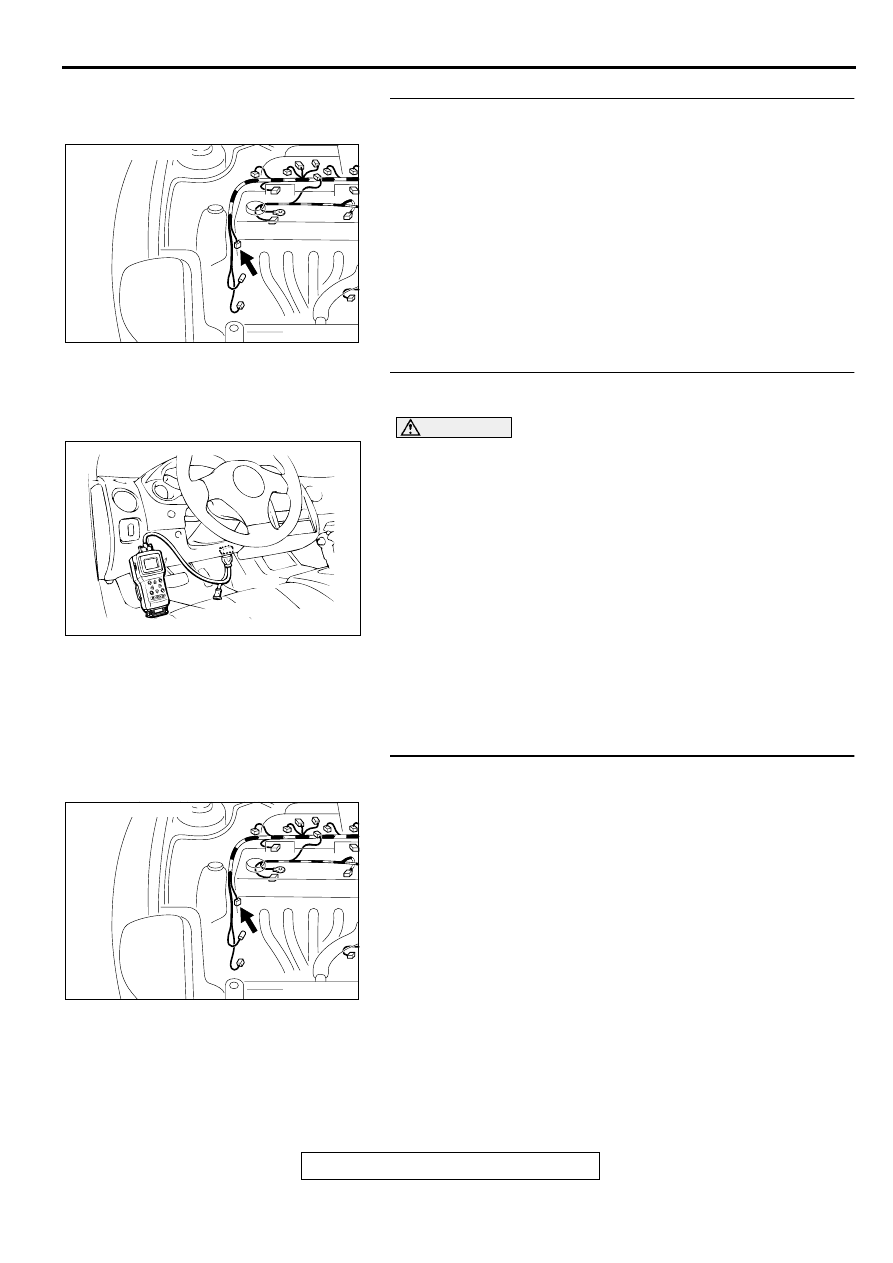
STEP 3. Check connector B-20 at the crankshaft position
sensor for damage.
Q: Is the connector in good condition?
YES : Go to Step 4.
NO : Repair or replace it. Refer to GROUP 00E, Harness
Connector Inspection (
STEP 4. Using scan tool MB991502, check data list item 22:
Crankshaft Position Sensor.
CAUTION
To prevent damage to scan tool MB991502, always turn the
ignition switch to the "LOCK" (OFF) position before
connecting or disconnecting scan tool MB991502.
(1) Connect scan tool MB991502 to the data link connector.
(2) Turn the ignition switch to the "ON" position.
(3) Set scan tool MB991502 to the data reading mode for item
22, Crankshaft Position Sensor.
•
The tachometer and engine speed indicated on the scan
tool should much.
(4) Turn the ignition switch to the "LOCK" (OFF) position.
Q: Is the sensor operating properly?
YES : It can be assumed that this malfunction is intermittent.
Refer to GROUP 00, How to Use Troubleshooting/
Inspection Service Points (
NO : Replace the ECM or PCM. Then go to Step 20.
STEP 5. Check connector B-20 at the crankshaft position
sensor for damage.
Q: Is the connector in good condition?
YES : Go to Step 6.
NO : Repair or replace it. Refer to GROUP 00E, Harness
Connector Inspection (
AK000546AB
CONNECTOR:C-20
AKX01177
16 PIN
MB991502
AB
AK000546AB
CONNECTOR:C-20
MULTIPORT FUEL INJECTION (MFI) DIAGNOSIS
TSB Revision
MULTIPORT FUEL INJECTION (MFI) <2.4L ENGINE>
13A-185
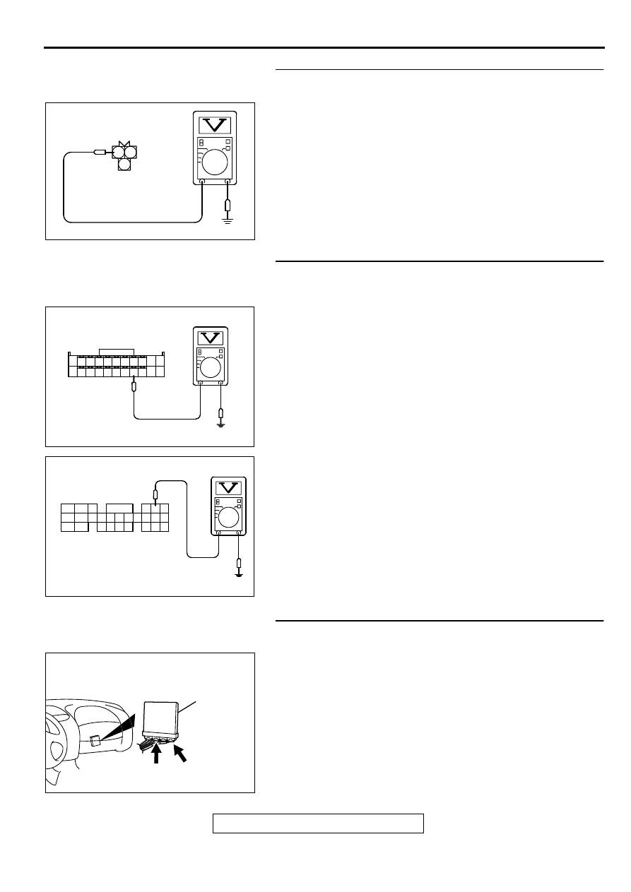
STEP 6. Check the sensor supply voltage at crankshaft
position sensor harness side connector B-20.
(1) Disconnect the connector B-20 and measure at the harness
side.
(2) Turn the ignition switch to the "ON" position.
(3) Measure the voltage between terminal 2 and ground.
•
Voltage should be between 4.8 and 5.2 volts
(4) Turn the ignition switch to the "LOCK" (OFF) position.
Q: Is the voltage normal?
YES : Go to Step 11.
NO : Go to Step 7.
STEP 7. Check the sensor supply voltage at ECM
connector C-60 <M/T> or PCM connector C-54 <A/T> by
backprobing
(1) Do not disconnect the ECM connector C-60 <M/T> or PCM
connector C-54 <A/T>.
(2) Disconnect the crankshaft position sensor connector B-20.
(3) Turn the ignition switch to the "ON" position.
(4) Measure the voltage between terminal 89 <M/T> or 45 <A/
T> and ground by backprobing.
•
Voltage should be between 4.8 and 5.2 volts.
(5) Turn the ignition switch to the "LOCK" (OFF) position.
Q: Is the voltage normal?
YES : Go to Step 8.
NO : Go to Step 9.
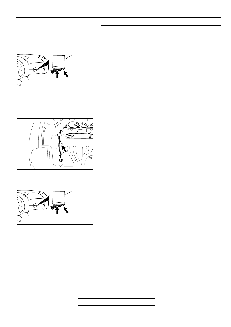
STEP 8. Check connector C-60 at ECM <M/T> or connector
C-54 at PCM <A/T> for damage.
Q: Is the connector in good condition?
YES : Repair it because of open circuit between crankshaft
position sensor connector B-20 terminal 2 and ECM
connector C-60 terminal 89 <M/T> or PCM connector
C-54 terminal 45 <A/T>. Then go to Step 20.
NO : Repair or replace it. Refer to GROUP 00E, Harness
Connector Inspection (
AKX01416 AC
2 1
3
B-20 HARNESS
SIDE CONNECTOR
AK000296
7172 73 74 75 76 77 78 79 80 81
82 83 84 85 86 87 88 89 90
92
91
AC
<M/T>
C-60 CONNECTOR
HARNESS SIDE VIEW
AK000297
C-54 CONNECTOR
HARNESS SIDE VIEW
46
57
66
45
56
65
44
55
43
49
54
64
42
48
59
41
47
58
53
63
52
62
51
61
50
60
AD
<A/T>
AK000280
C-54
C-60
ECM<M/T>
OR
PCM<A/T>
CONNECTORS:C-60<M/T>,C-54<A/T>
BB
MULTIPORT FUEL INJECTION (MFI) DIAGNOSIS
TSB Revision
MULTIPORT FUEL INJECTION (MFI) <2.4L ENGINE>
13A-186
STEP 9. Check connector C-60 at ECM <M/T> or connector
C-54 at PCM <A/T> for damage.
Q: Is the connector in good condition?
YES : Go to Step 10.
NO : Repair or replace it. Refer to GROUP 00E, Harness
Connector Inspection (
STEP 10. Check for short circuit to ground between
crankshaft position sensor connector B-20 terminal 2 and
ECM connector C-60 terminal 89 <M/T> or PCM connector
C-54 terminal 45 <A/T>.
Q: Is the harness wire in good condition?
YES : Replace the ECM or PCM. Then go to Step 20.
NO : Repair it. Then go to Step 20.
AK000280
C-54
C-60
ECM<M/T>
OR
PCM<A/T>
CONNECTORS:C-60<M/T>,C-54<A/T>
BB
AK000546AB
CONNECTOR:C-20
AK000280
C-54
C-60
ECM<M/T>
OR
PCM<A/T>
CONNECTORS:C-60<M/T>,C-54<A/T>
BB
Нет комментариевНе стесняйтесь поделиться с нами вашим ценным мнением.
Текст