Mitsubishi Eclipse / Eclipse Spyder (2000-2002). Service and repair manual — part 559
REAR SUSPENSION ASSEMBLY
TSB Revision
REAR SUSPENSION
34-9
INSTALLATION SERVICE POINT
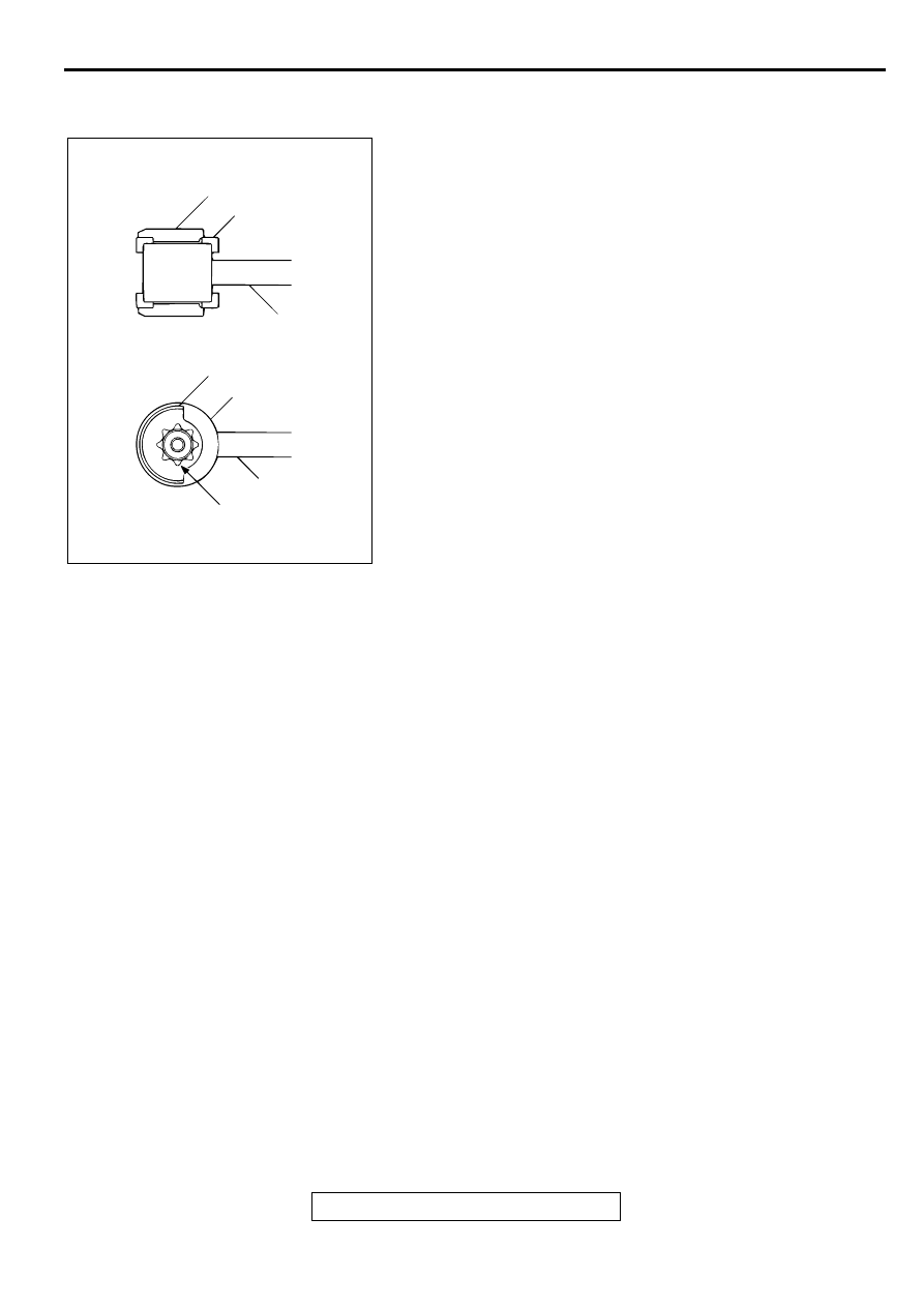
>>A<< STOPPER B/STOPPER A INSTALLATION
1. Install stopper B in the shown direction.
2. Install stopper A in the shown direction while checking that
the notches on stopper A are engaged with the projections
on the trailing arm bushing.
INSPECTION
M1341001100033
Check crossmember for cracks or other damage.
AC001059
STOPPER A
STOPPER A
STOPPER B
STOPPER B
TRAILING ARM
TRAILING ARM
NOTCHES AND PROJECTIONS
AB
UPPER ARM ASSEMBLY
TSB Revision
REAR SUSPENSION
34-10
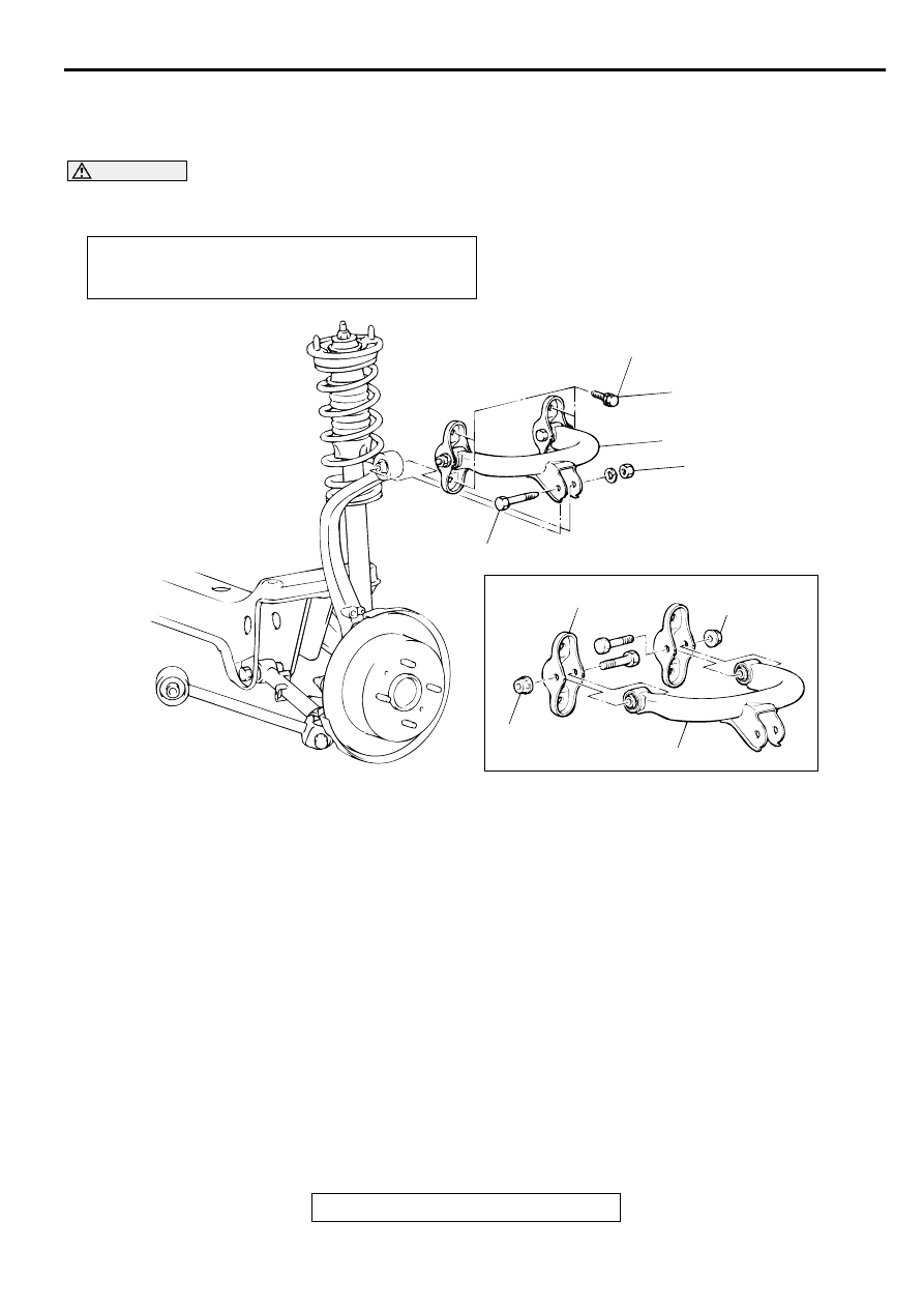
UPPER A RM A SSEM B LY
REMOVAL AND INSTALLATION
M1341003600078
CAUTION
*
: Indicates parts which should be temporarily tightened, and then fully tightened with the vehicle on
the ground in the unladen condition.
Post-installation Operation
•
Wheel Alignment Check and Adjustment (Refer to
AC001060
39 ± 5 N·m
29 ± 3 ft-lb
98 ± 10 N·m*
73 ± 7 ft-lb*
57 ± 7 N·m
42 ± 5 ft-lb
57 ± 7 N·m
42 ± 5 ft-lb
4
5
1
2
3
AB
REMOVAL STEPS
1.
UPPER ARM AND KNUCKLE
CONNECTING BOLT
2.
UPPER ARM ASSEMBLY
MOUNTING BOLTS
3.
UPPER ARM ASSEMBLY
>>A<<
4.
UPPER ARM BRACKET
5.
UPPER ARM
REMOVAL STEPS (Continued)
UPPER ARM ASSEMBLY
TSB Revision
REAR SUSPENSION
34-11
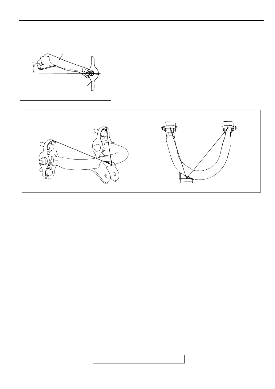
INSTALLATION SERVICE POINT
>>A<< UPPER ARM BRACKET INSTALLATION
Install the upper arm bracket so that the dimension shown in
the illustration is at the standard value.
Standard value (A): 37.2
±
2 mm (1.46
±
0.08 inches)
NOTE: Refer to distances B and C shown in the illustration to
check the installation angle of the upper arm bracket.
INSPECTION
M1341003700075
•
Check the bushings for wear and deterioration.
•
Check the upper arm for bends or damage.
•
Check all bolts for condition and straightness.
AC001061 AB
A
UPPER ARM
UPPER ARM BRACKET
AC001062
B: 220.1 mm (8.67 in)
C: 274.4 mm (10.80 in)
B
C
B
C
AB
TRAILING ARM ASSEMBLY
TSB Revision
REAR SUSPENSION
34-12
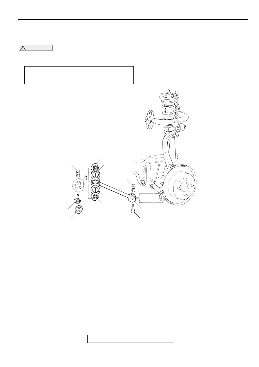
TR AILING A R M A SSEM BLY
REMOVAL AND INSTALLATION
M1341002200033
CAUTION
*
: Indicates parts which should be temporarily tightened, and then fully tightened with the vehicle on
the ground in the unladen condition.
Post-installation Operation
•
Wheel Alignment Check and Adjustment (Refer to
AC001063
147 ± 10 N·m*
109 ± 7 ft-lb*
128 ± 9 N·m*
94 ± 7 ft-lb*
4
5
5
4
3
2
6
1
AB
REMOVAL STEPS
1.
KNUCKLE AND TRAILING ARM
ASSEMBLY CONNECTING BOLT
2.
GROMMET
3.
TRAILING ARM ASSEMBLY
MOUNTING BOLT
>>A<<
4.
STOPPER A
>>A<<
5.
STOPPER B
6.
TRAILING ARM ASSEMBLY
REMOVAL STEPS (Continued)
Нет комментариевНе стесняйтесь поделиться с нами вашим ценным мнением.
Текст