Mitsubishi Eclipse / Eclipse Spyder (2000-2002). Service and repair manual — part 593
TRACTION CONTROL SYSTEM (TCL) DIAGNOSIS
TSB Revision
TRACTION CONTROL SYSTEM (TCL)
35C-7
5. Turn the ignition switch to the "LOCK" (OFF) position.
6. Disconnect special tool MB991529.
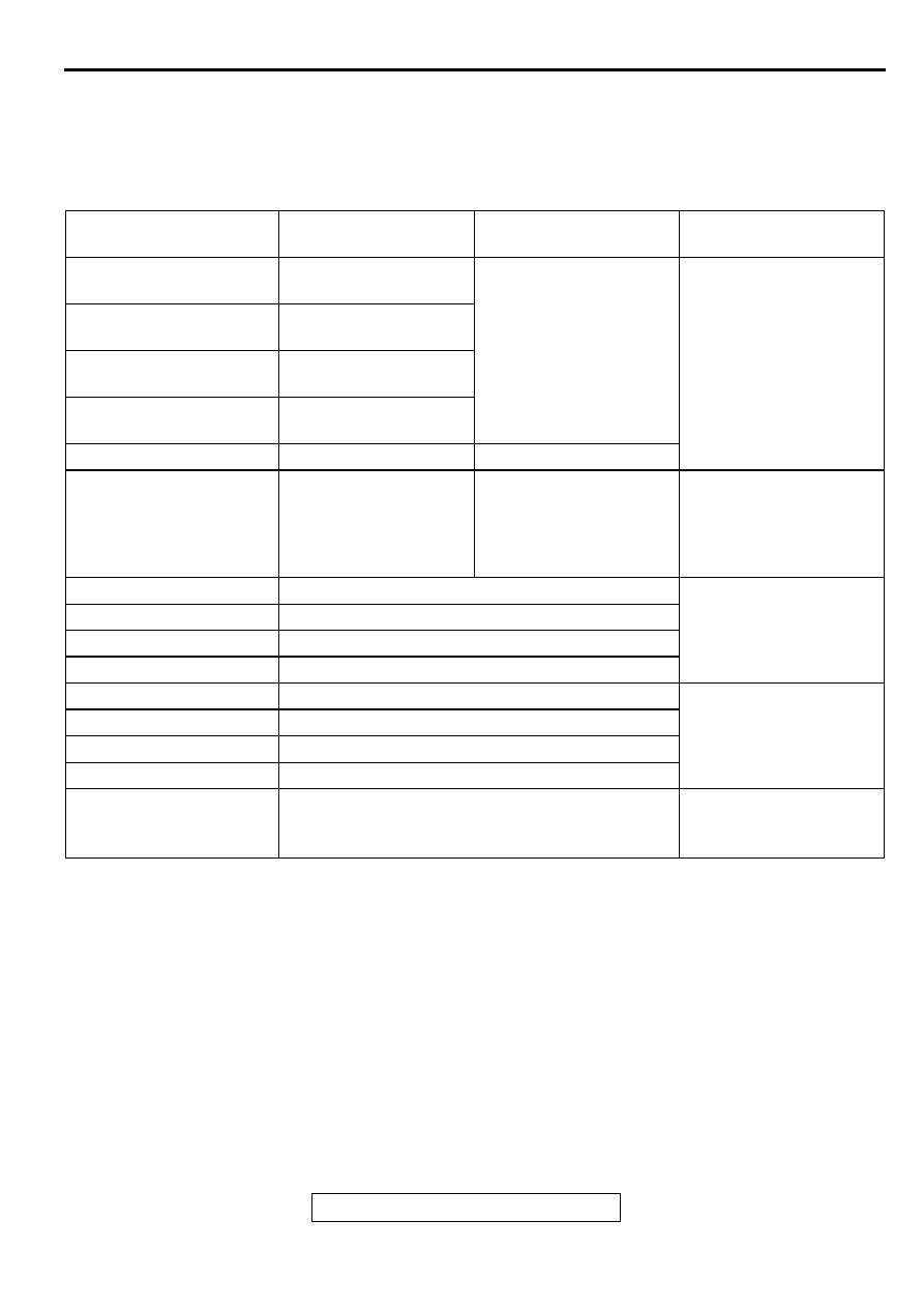
DIAGNOSTIC TROUBLE CODE CHART
M1354000600046
Follow the inspection chart that is appropriate for the
diagnostic trouble code.
DIAGNOSTIC TROUBLE
CODE NO.
INSPECTION ITEM
DIAGNOSTIC CONTENT REFERENCE PAGE
11
Front right wheel speed
sensor
Open circuit or short
circuit
GROUP 35B, Diagnostic
Trouble Code Procedures
12
Front left wheel speed
sensor
13
Rear right wheel speed
sensor
14
Rear left wheel speed
sensor
15
Wheel speed sensor
Abnormal output signal
16
Power supply system
ABS-ECU power supply
voltage below or above
the standard value. Not
displayed if the voltage
recovers.
Check the battery. (Refer
to GROUP 54A, Battery
−
On-vehicle Service
−
Battery Check
.)
21
Front right wheel speed sensor
GROUP 35B, Diagnostic
Trouble Code Procedures
22
Front left wheel speed sensor
23
Rear right wheel speed sensor
24
Rear left wheel speed sensor
31
TCL front left solenoid valve (IN)
32
TCL front left solenoid valve (OUT)
33
TCL front right solenoid valve (IN)
34
TCL front right solenoid valve (OUT)
38
Stoplight switch system
GROUP 35B, Diagnostic
Trouble Code Procedures
TRACTION CONTROL SYSTEM (TCL) DIAGNOSIS
TSB Revision
TRACTION CONTROL SYSTEM (TCL)
35C-8
DIAGNOSTIC TROUBLE CODE PROCEDURES
DTC 31, 32, 33, 34: TCL Solenoid Valve inside Hydraulic Unit (Open Circuit or Short Circuit) /DTC 41,
42, 43, 44, 45, 46, 47, 48: ABS Solenoid Valve inside Hydraulic Unit (Open Circuit or Short Circuit) /
DTC 51: Valve Power Supply /DTC 53: Pump Motor
41
ABS front right solenoid valve (IN)
42
ABS front left solenoid valve (IN)
43
ABS rear right solenoid valve (IN)
44
ABS rear left solenoid valve (IN)
45
ABS front right solenoid valve (OUT)
46
ABS front left solenoid valve (OUT)
47
ABS rear right solenoid valve (OUT)
48
ABS rear left solenoid valve (OUT)
51
Valve power supply
53
Pump motor
63
ABS-ECU
Replace the hydraulic unit
(Integrated with ABS-
ECU). (Refer to GROUP
35B, Hydraulic Unit
.)
DIAGNOSTIC TROUBLE
CODE NO.
INSPECTION ITEM
DIAGNOSTIC CONTENT REFERENCE PAGE
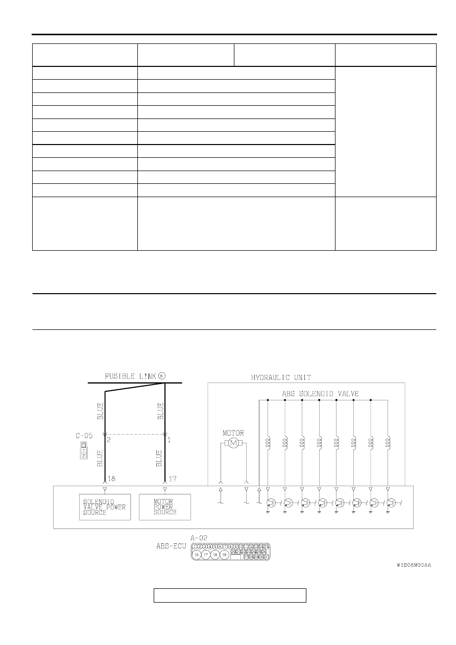
Solenoid Valve and Motor Power Supply Circuit
TRACTION CONTROL SYSTEM (TCL) DIAGNOSIS
TSB Revision
TRACTION CONTROL SYSTEM (TCL)
35C-9
CIRCUIT OPERATION
Power is continuously supplied to the ABS-ECU
through fusible link number 6 to operate the solenoid
valves and motor. The ABS-ECU supplies power to
the solenoids. If controls each solenoid by switching
the ground circuit ON or OFF, depending on driving
conditions.
TCL DTC SET CONDITIONS
These codes are displayed if the power supply circuit
of solenoid valve or motor is open or short.
TROUBLESHOOTING HINTS (The most likely
causes for these DTCs are to set are:)
•
Damaged wiring harness or connector
•
Malfunction of the hydraulic unit (integrated with
ABS-ECU)
DIAGNOSIS
Required Special Tools:
•
MB991223: Harness Set
•
MB991502: Scan Tool (MUT-II)
•
MB991529: Diagnostic Trouble Code Check Harness
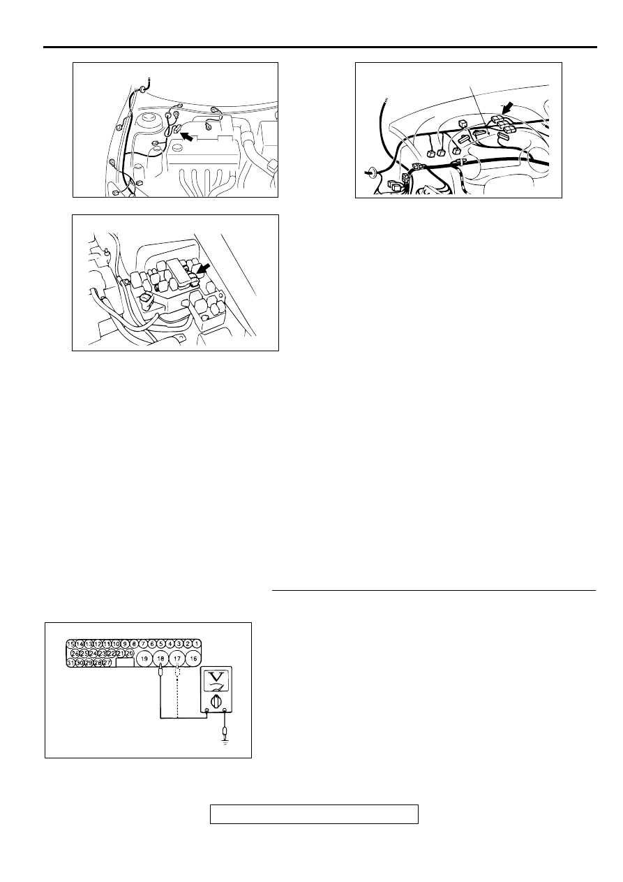
STEP 1. Check the solenoid valve or motor power supply
circuit at the ABS-ECU connector A-02.
(1) Disconnect the ABS-ECU connector A-02 and measure at
the harness side.
(2) Measure the voltages between terminal 18 and ground, and
17 and ground.
Q: Are the voltages approximately 12 volts (battery
positive voltage)?
YES : Replace the hydraulic unit (integrated with ABS-ECU)
(Refer to GROUP 35B, Hydraulic Unit
.).
Then go to Step 3.
NO : Go to Step 2.
AC001985
CONNECTOR: A-02
AD
AC004431AB
CONNECTOR: C-05
COMBINATION METER
AC004422 AB
FUSIBLE LINK (6)
AC000945
A-02 (HARNESS SIDE)
AB
TRACTION CONTROL SYSTEM (TCL) DIAGNOSIS
TSB Revision
TRACTION CONTROL SYSTEM (TCL)
35C-10
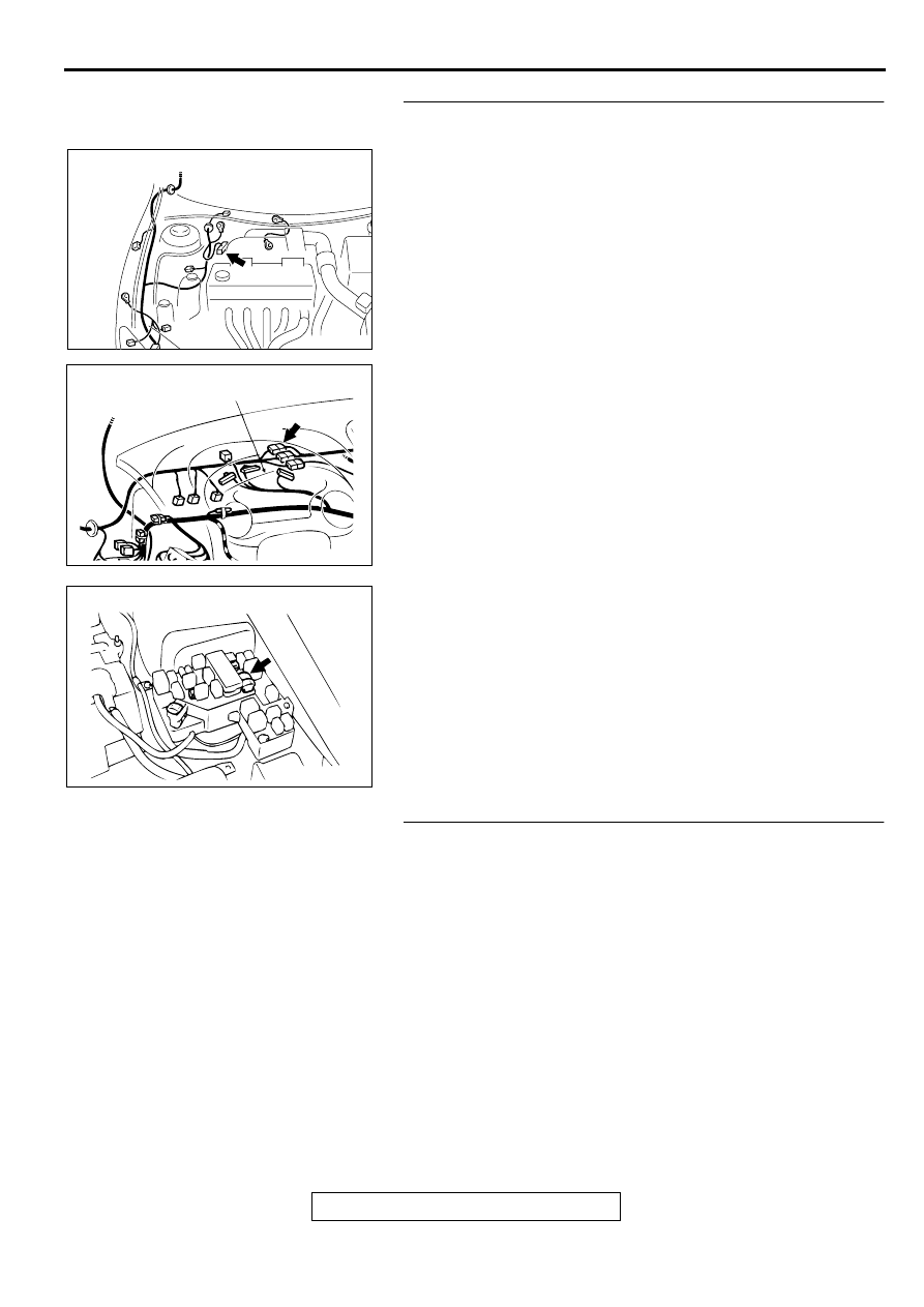
STEP 2. Check the harness wire between the fusible link
number 6 and the ABS-ECU connector A-02.
NOTE: After inspecting the intermediate connector C-05,
inspect the wires. If the intermediate connector C-05 is
damaged, repair or replace it. Refer to GROUP 00E, Harness
Connector Inspection
. If the connector has been
repaired or replaced, go to Step 3.
Q: Is any of the harness wires between the fusible link
number 6 and the ABS-ECU connector A-02 damaged?
YES : Repair it and then go to Step 3.
NO : Go to Step 3.
STEP 3. Check the diagnostic trouble codes.
Q: Does any of the diagnostic trouble codes 31, 32, 33, 34,
41, 42, 43, 44, 45, 46, 47, 48, 51, or 53 reset?
YES : Return to Step 1.
NO : This diagnosis is complete.
AC001985
CONNECTOR: A-02
AD
AC004431AB
CONNECTOR: C-05
COMBINATION METER
AC004422 AB
FUSIBLE LINK (6)
Нет комментариевНе стесняйтесь поделиться с нами вашим ценным мнением.
Текст