Mitsubishi Eclipse / Eclipse Spyder (2000-2002). Service and repair manual — part 295
MULTIPORT FUEL INJECTION (MFI) DIAGNOSIS
TSB Revision
MULTIPORT FUEL INJECTION (MFI) <3.0L ENGINE>
13B-379
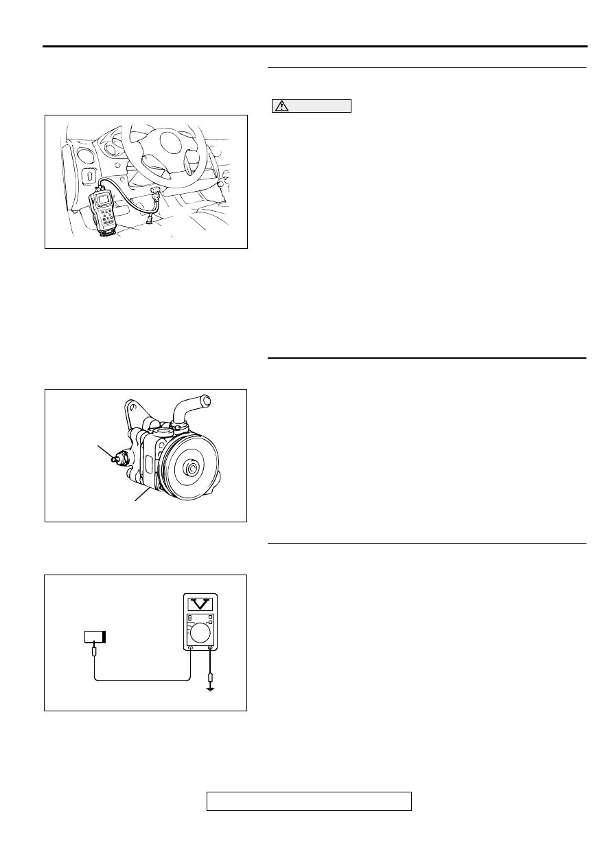
STEP 4. Using scan tool MB991502, check data list item 27:
Power Steering Pressure Switch.
CAUTION
To prevent damage to scan tool MB991502, always turn the
ignition switch to the "LOCK" (OFF) position before
connecting or disconnecting scan tool MB991502.
(1) Connect scan tool MB991502 to the data link connector.
(2) Start the engine and run at idle.
(3) Set scan tool MB991502 to the data reading mode for item
27, Power Steering Pressure Switch.
•
If the steering wheel is stopped while idling, "OFF" will
be displayed.
•
If the steering wheel is steered while idling, "ON" will be
displayed.
(4) Turn the ignition switch to the "LOCK" (OFF) position.
Q: Is the sensor operating properly?
YES : It can be assumed that this malfunction is intermittent.
Refer to GROUP 00, How to Use Troubleshooting/
Inspection Service Points (
NO : Replace the ECM or PCM. Then go to Step 14.
STEP 5. Check connector B-19 at power steering pressure
switch for damage.
Q: Is the connector in good condition?
YES : Go to Step 6.
NO : Repair or replace it. Refer to GROUP 00E, Harness
Connector Inspection (
). Then go to Step 14.
STEP 6. Check the power supply voltage at power steering
pressure switch harness side connector B-19.
(1) Disconnect the connector B-19 and measure at the harness
side.
(2) Turn the ignition switch to the "ON" position.
(3) Measure the voltage between terminal 1 and ground.
•
Voltage should be battery positive voltage.
(4) Turn the ignition switch to the "LOCK" (OFF) position.
Q: Is the voltage normal?
YES : Go to Step 11.
NO : Go to Step 7.
AKX01177
16 PIN
MB991502
AB
ACX02522 AC
CONNECTOR : B-19
POWER
STEERING
PRESSURE
SWITCH
POWER STEERING
OIL PUMP
AK000260AB
1
B-19 HARNESS
SIDE CONNECTOR
MULTIPORT FUEL INJECTION (MFI) DIAGNOSIS
TSB Revision
MULTIPORT FUEL INJECTION (MFI) <3.0L ENGINE>
13B-380
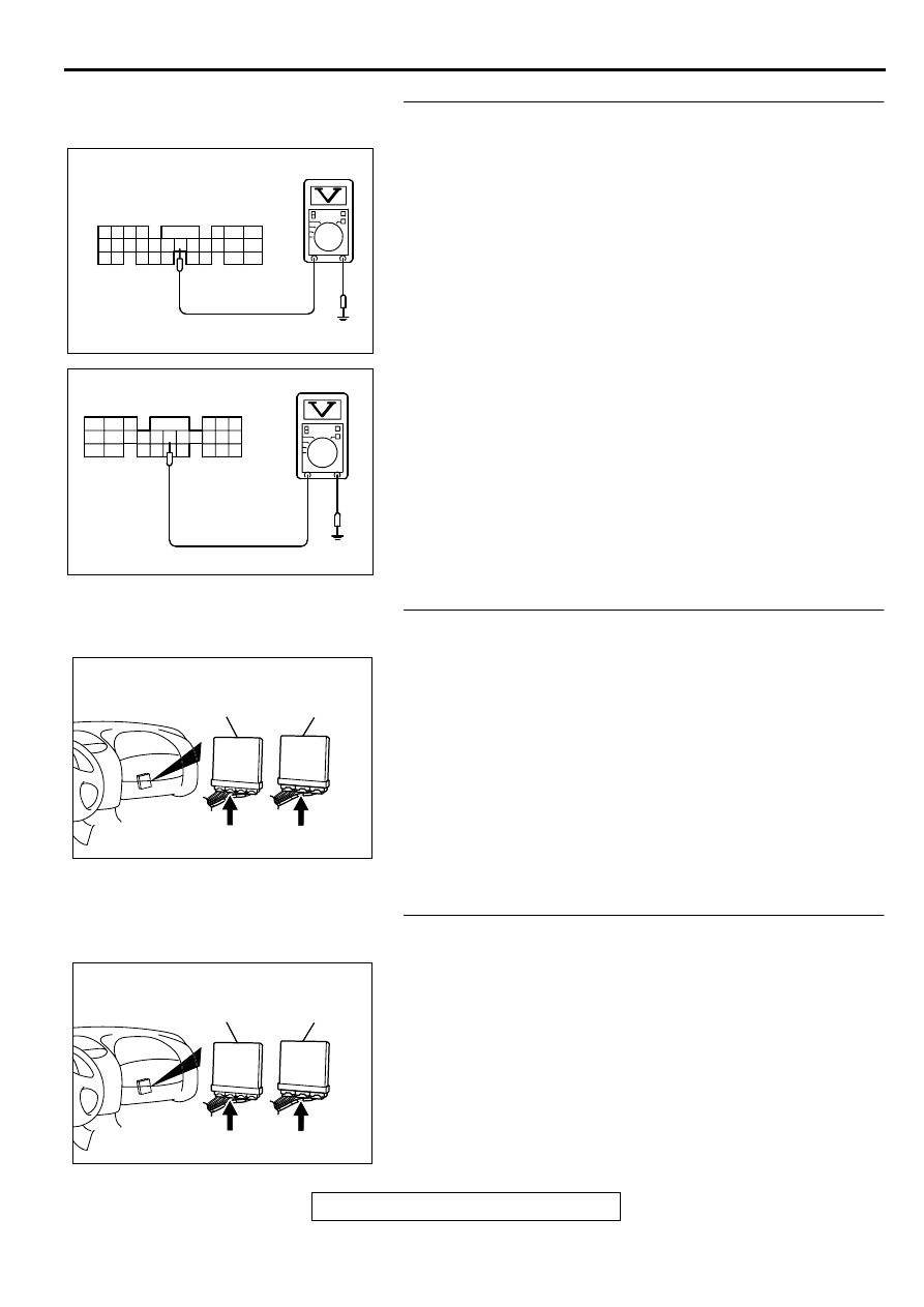
STEP 7. Check the power supply voltage at ECM connector
C-58 <M/T> or PCM connector C-55 <A/T> by backprobing
(1) Do not disconnect the ECM connector C-58 <M/T> or PCM
connector C-55 <A/T>.
(2) Disconnect the power steering pressure switch connector
B-19.
(3) Turn the ignition switch to the "ON" position.
(4) Measure the voltage between terminal 54 <M/T> or 52 <A/
T> and ground by backprobing.
•
Voltage should be between battery positive voltage.
(5) Turn the ignition switch to the "LOCK" (OFF) position.
Q: Is the voltage normal?
YES : Go to Step 8.
NO : Go to Step 9.
STEP 8. Check connector C-58 at ECM <M/T> or connector
C-55 at PCM <A/T> for damage.
Q: Is the connector in good condition?
YES : Check connector B-47 at intermediate connector for
damage, and repair or replace as required. Refer to
GROUP 00E, Harness Connector Inspection (
). If intermediate connector is in good condition,
repair harness wire between power steering pressure
switch connector B-19 terminal 1 and ECM connector
C-58 terminal 54 <M/T> or PCM connector C-55
terminal 52 <A/T> because of open circuit. Then go to
Step 14.
NO : Repair or replace it. Refer to GROUP 00E, Harness
Connector Inspection (
). Then go to Step 14.
STEP 9. Check connector C-58 at ECM <M/T> or connector
C-55 at PCM <A/T> for damage.
Q: Is the connector in good condition?
YES : Go to Step 10.
NO : Repair or replace it. Refer to GROUP 00E, Harness
Connector Inspection (
). Then go to Step 14.
AK000261
4142 43 44
48
50 51
49
52 53 54 55 56 57 58 59
45 46 47
60 61
62 63 64
65
67 68
66
AC
C-58 CONNECTOR
HARNESS SIDE VIEW
<M/T>
AKX01552
41
AE
C-55 CONNECTOR
HARNESS SIDE VIEW
42 43
44 45 46
47 48 49 50 51 52 53 54 55 56 57
58 59
60 61
63
64
66
<A/T>
65
AK000225
CONNECTOR : C-58<M/T>, C-55<A/T>
C-55
C-58
PCM<A/T>
ECM<M/T>
AI
AK000225
CONNECTOR : C-58<M/T>, C-55<A/T>
C-55
C-58
PCM<A/T>
ECM<M/T>
AI
MULTIPORT FUEL INJECTION (MFI) DIAGNOSIS
TSB Revision
MULTIPORT FUEL INJECTION (MFI) <3.0L ENGINE>
13B-381
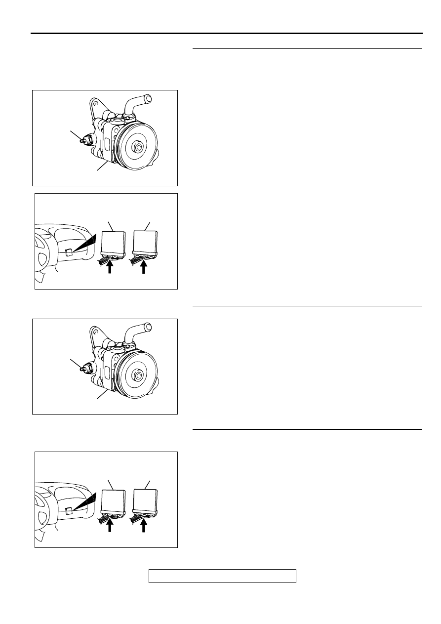
STEP 10. Check for short circuit to ground between power
steering pressure switch connector B-19 terminal 1 and
ECM connector C-58 terminal 54 <M/T> or PCM connector
C-55 terminal 52 <A/T>.
NOTE: Check harness after checking intermediate connector
B-47. If intermediate connector is damaged, repair or replace
them. Refer to GROUP 00E, Harness Connector Inspection
(
). Then go to Step 14.
Q: Is the harness wire in good condition?
YES : Replace the ECM or PCM. Then go to Step 14.
NO : Repair it. Then go to Step 14.
STEP 11. Replace the power steering pressure switch.
(1) Replace the power steering pressure switch.
(2) Check the trouble symptoms.
(3) Check the diagnostic trouble code (DTC).
Q: Is the DTC P0551 is output?
YES : Go to Step 12.
NO : Go to Step 14.
STEP 12. Check connector C-58 at ECM <M/T> or
connector C-55 at PCM <A/T> for damage.
Q: Is the connector in good condition?
YES : Go to Step 13.
NO : Repair or replace it. Refer to GROUP 00E, Harness
Connector Inspection (
). Then go to Step 14.
ACX02522 AC
CONNECTOR : B-19
POWER
STEERING
PRESSURE
SWITCH
POWER STEERING
OIL PUMP
AK000225
CONNECTOR : C-58<M/T>, C-55<A/T>
C-55
C-58
PCM<A/T>
ECM<M/T>
AI
ACX02522 AC
CONNECTOR : B-19
POWER
STEERING
PRESSURE
SWITCH
POWER STEERING
OIL PUMP
AK000225
CONNECTOR : C-58<M/T>, C-55<A/T>
C-55
C-58
PCM<A/T>
ECM<M/T>
AI
MULTIPORT FUEL INJECTION (MFI) DIAGNOSIS
TSB Revision
MULTIPORT FUEL INJECTION (MFI) <3.0L ENGINE>
13B-382
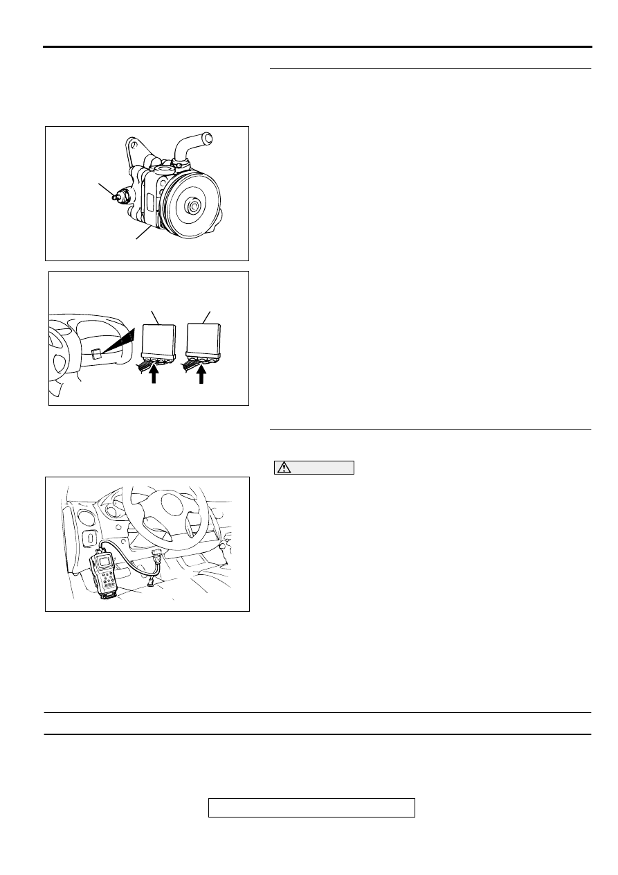
STEP 13. Check for harness damage between power
steering pressure switch connector B-19 terminal 1 and
ECM connector C-58 terminal 54 <M/T> or PCM connector
C-55 terminal 52 <A/T>.
NOTE: Check harness after checking intermediate connector
B-47. If intermediate connector is damaged, repair or replace
them. Refer to GROUP 00E, Harness Connector Inspection
(
). Then go to Step 14.
Q: Is the harness wire in good condition?
YES : Replace the ECM or PCM. Then go to Step 14.
NO : Repair it. Then go to Step 14.
STEP 14. Using scan tool MB991502, check data list item
27: Power Steering Pressure Switch.
CAUTION
To prevent damage to scan tool MB991502, always turn the
ignition switch to the "LOCK" (OFF) position before
connecting or disconnecting scan tool MB991502.
(1) Connect scan tool MB991502 to the data link connector.
(2) Start the engine and run at idle.
(3) Set scan tool MB991502 to the data reading mode for item
27, Power Steering Pressure Switch.
•
If the steering wheel is stopped while idling, "OFF" will
be displayed.
•
If the steering wheel is steered while idling, "ON" will be
displayed.
(4) Turn the ignition switch to the "LOCK" (OFF) position.
Q: Is the switch operating properly?
YES : The inspection is complete.
NO : Retry the troubleshooting.
DTC P0705: Transmission Range Sensor Circuit Malfunction (PRNDL Input)
TECHNICAL DESCRIPTION
•
When a malfunction of the park/neutral position
switch is detected, the transaxle control CPU in
the powertrain control module (PCM) outputs a
malfunction signal to the engine control CPU in
the PCM.
ACX02522 AC
CONNECTOR : B-19
POWER
STEERING
PRESSURE
SWITCH
POWER STEERING
OIL PUMP
AK000225
CONNECTOR : C-58<M/T>, C-55<A/T>
C-55
C-58
PCM<A/T>
ECM<M/T>
AI
AKX01177
16 PIN
MB991502
AB
Нет комментариевНе стесняйтесь поделиться с нами вашим ценным мнением.
Текст