Mitsubishi Eclipse / Eclipse Spyder (2000-2002). Service and repair manual — part 457
AUTOMATIC TRANSAXLE DIAGNOSIS
TSB Revision
AUTOMATIC TRANSAXLE
23A-120
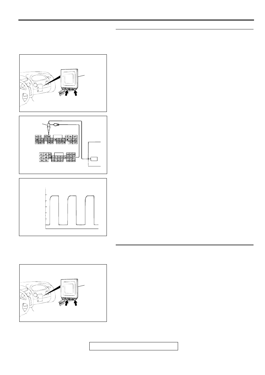
STEP 8. Using the oscilloscope, check the waveform at
PCM connectors C-54 <2.4L Engine> or C-55 <3.0L
Engine> and C-61 <2.4L Engine> or C-63 <3.0L Engine> by
backprobing.
(1) Do not disconnect connectors C-54 <2.4L Engine> or C-55
<3.0L Engine> and C-61 <2.4L Engine> or C-63 <3.0L
Engine>.
(2) Connect an oscilloscope probe to PCM connector C-54
<2.4L Engine> or C-55 <3.0L Engine> terminal 57 and to
PCM connector C-61 <2.4L Engine> or C-63 <3.0L Engine>
terminal 104 by backprobing.
(3) Start the engine and run at constant speed of 50km/h
(31mph). (Gear range: 3rd gear)
(4) Check the waveform.
•
The waveform should show a pattern similar to the
illustration. The maximum value should be 4.8 volts and
more and the minimum value 0.8 volts and less. The
output waveform should not contain the noise.
(5) Turn the ignition switch to "LOCK" (OFF) position.
Q: Is the waveform normal?
YES : Go to Step 9.
NO : Go to Step 10.
STEP 9. Check connectors C-54 <2.4L Engine> or C-55
<3.0L Engine> and C-61 <2.4L Engine> or C-63 <3.0L
Engine> at PCM for damage.
Q: Are the connectors in good condition?
YES : Go to Step 4.
NO : Repair or replace it. Refer to GROUP 00E, Harness
Connector Inspection
.
AC001657
CONNECTORS: C-54 <2.4L ENGINE> OR
C-55 <3.0L ENGINE>, C-61 <2.4L ENGINE>
OR C-63 <3.0L ENGINE>
PCM
AM
C-54 <2.4L ENGINE>
OR
C-55 <3.0L ENGINE>
C-61 <2.4L ENGINE>
OR
C-63 <3.0L ENGINE>
AC001900
C-61 <2.4L ENGINE> OR C-63 <3.0L ENGINE>
CONNECTOR HARNESS SIDE VIEW
C-54 <2.4L ENGINE> OR C-55 <3.0L ENGINE>
CONNECTOR HARNESS SIDE VIEW
OSCILLO-
SCOPE
PROBE
AD
ACX02131
NORMAL WAVEFORM
AB
(V)
5
0
AC001657
CONNECTORS: C-54 <2.4L ENGINE> OR
C-55 <3.0L ENGINE>, C-61 <2.4L ENGINE>
OR C-63 <3.0L ENGINE>
PCM
AM
C-54 <2.4L ENGINE>
OR
C-55 <3.0L ENGINE>
C-61 <2.4L ENGINE>
OR
C-63 <3.0L ENGINE>
AUTOMATIC TRANSAXLE DIAGNOSIS
TSB Revision
AUTOMATIC TRANSAXLE
23A-121
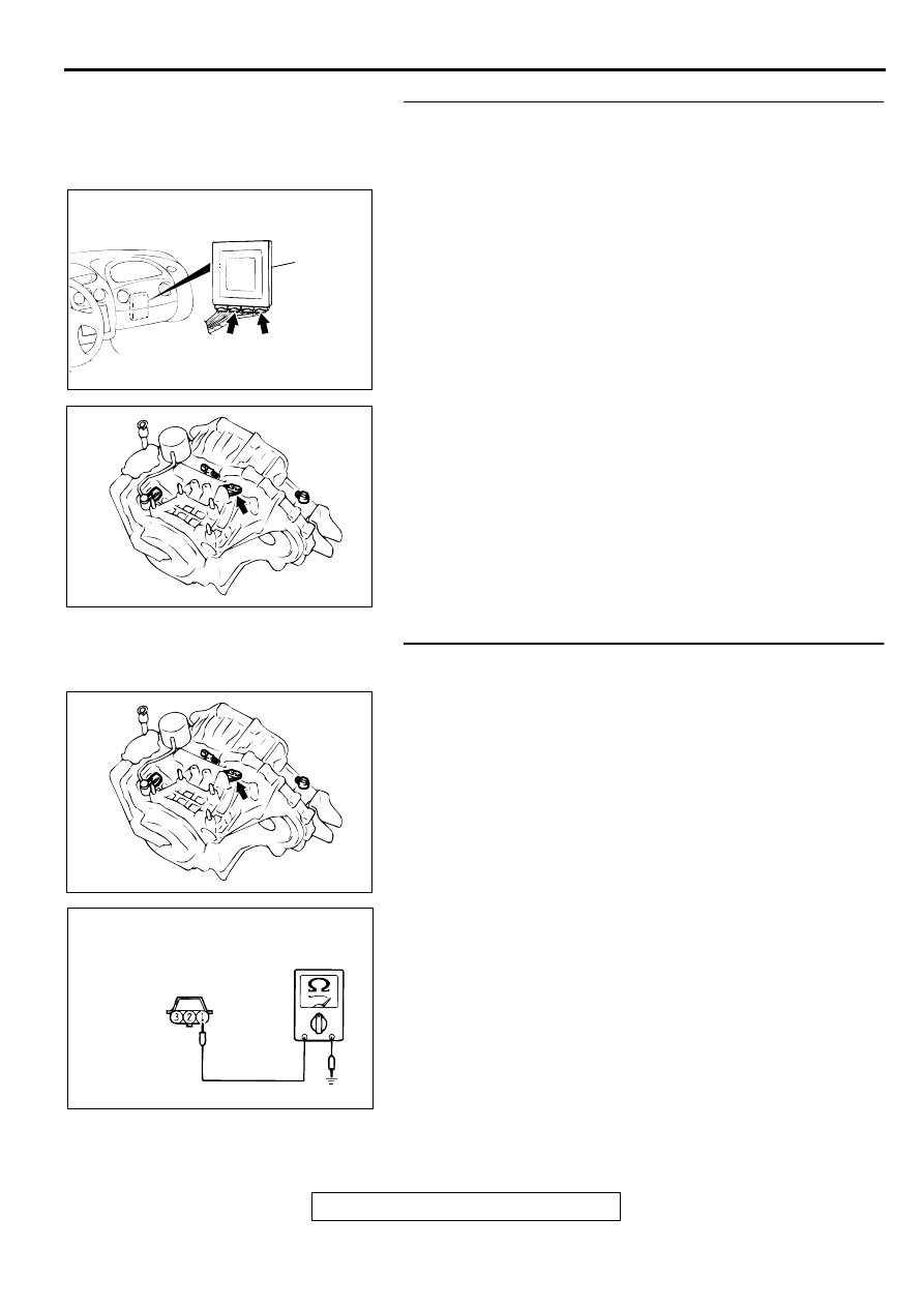
STEP 10. Check connectors C-54 <2.4L Engine> or C-55
<3.0L Engine> and C-61 <2.4L Engine> or C-63 <3.0L
Engine> at PCM and B-38 at output shaft speed sensor for
damage.
Q: Are the connectors in good condition?
YES : Go to Step 11.
NO : Repair or replace it. Refer to GROUP 00E, Harness
Connector Inspection
.
STEP 11. Check the continuity at output shaft speed
sensor connector B-38.
(1) Disconnect connector B-38 and measure at the harness
side.
(2) Check for the continuity between terminal 1 and ground.
•
Should be less than 2 ohm.
Q: Is the continuity normal?
YES : Go to Step 12.
NO : Repair it because of harness open circuit or damage
between output shaft speed sensor connector B-38
terminal 1 and PCM connector C-54 <2.4L Engine> or
C-55 <3.0L Engine> terminal 57.
AC001657
CONNECTORS: C-54 <2.4L ENGINE> OR
C-55 <3.0L ENGINE>, C-61 <2.4L ENGINE>
OR C-63 <3.0L ENGINE>
PCM
AM
C-54 <2.4L ENGINE>
OR
C-55 <3.0L ENGINE>
C-61 <2.4L ENGINE>
OR
C-63 <3.0L ENGINE>
AC001837AE
CONNECTOR: B-38
AC001837AE
CONNECTOR: B-38
ACX02136AE
HARNESS
CONNECTOR: B-38
AUTOMATIC TRANSAXLE DIAGNOSIS
TSB Revision
AUTOMATIC TRANSAXLE
23A-122
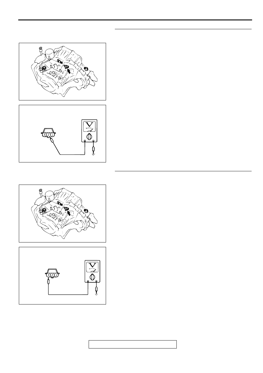
STEP 12. Check the sensor output voltage at output shaft
speed sensor connector B-38.
(1) Disconnect connector B-38 and measure at the harness
side.
(2) Turn the ignition switch to "ON" position.
(3) Measure the voltage between terminal 2 and ground.
•
Voltage should be between 4.8 and 5.2 volts.
(4) Turn the ignition switch to "LOCK" (OFF) position.
Q: Is the voltage normal?
YES : Go to Step 13.
NO : Repair it because of harness open circuit between
output shaft speed sensor connector B-108 terminal 2
and PCM connector C-61 <2.4L Engine> or C-63
<3.0L Engine> terminal 104.
STEP 13. Check the power supply voltage at output shaft
speed sensor connector B-38.
(1) Disconnect connector B-38 and measure at the harness
side.
(2) Turn the ignition switch to "ON" position.
(3) Measure the voltage between terminal 3 and ground.
•
Voltage should be battery positive voltage.
(4) Turn the ignition switch to "LOCK" (OFF) position.
Q: Is the voltage normal?
YES : Go to Step 15.
NO : Go to Step 14.
AC001837AE
CONNECTOR: B-38
ACX02135
HARNESS
CONNECTOR: B-38
AE
AC001837AE
CONNECTOR: B-38
ACX02134AE
HARNESS
CONNECTOR: B-38
AUTOMATIC TRANSAXLE DIAGNOSIS
TSB Revision
AUTOMATIC TRANSAXLE
23A-123
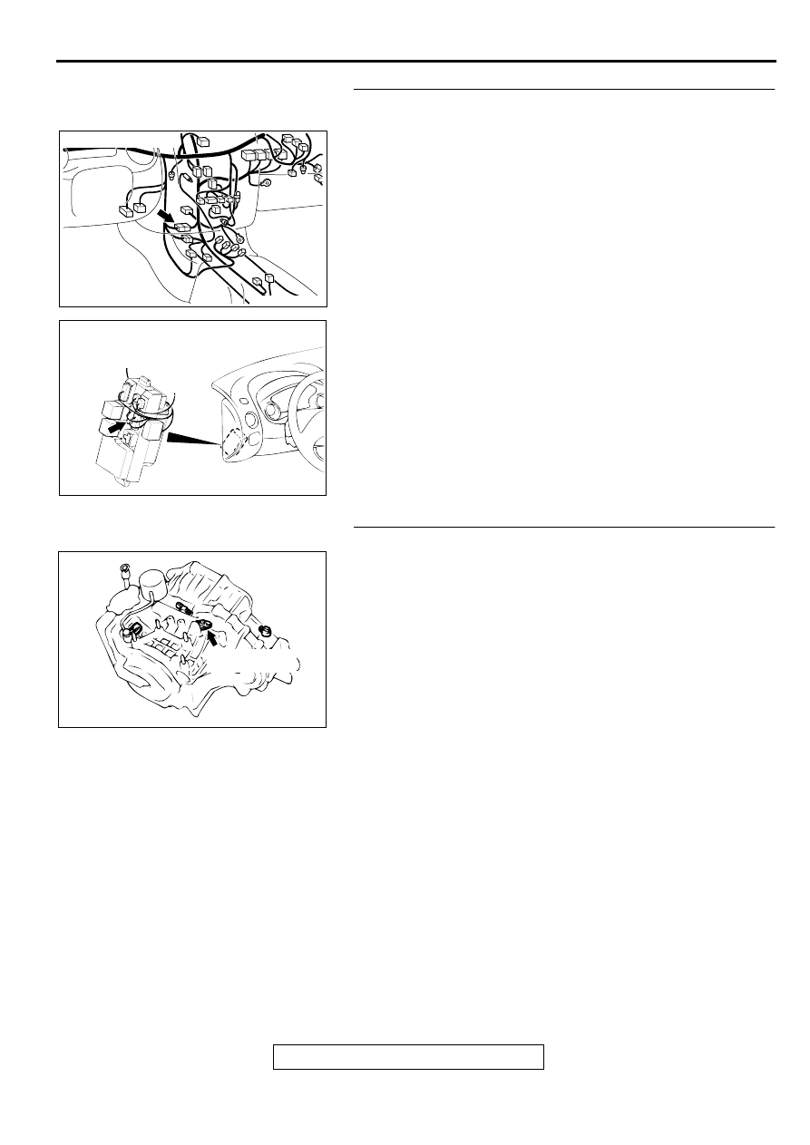
STEP 14. Check connectors C-28 at intermediate
connector and C-107 at junction block for damage.
Q: Are the connectors in good condition?
YES : Repair it because of harness open circuit or short
circuit to ground between output shaft speed sensor
connector B-38 terminal 3 and junction block
connector C-107 terminal 12.
NO : Repair or replace it. Refer to GROUP 00E, Harness
Connector Inspection
.
STEP 15. Replace the output shaft speed sensor.
(1) Replace the output shaft speed sensor. Refer to GROUP
23B, Transaxle
(2) Carry out a test drive.
(3) Read in the A/T diagnostic trouble code.
Q: Is the A/T diagnostic trouble code "23" output?
YES : Go to Step 18.
NO : The inspection is complete.
AC001741 AJ
CONNECTOR: C-28
AC001691
CONNECTOR: C-107
JUNCTION BLOCK
(FRONT VIEW)
AO
AC001837AD
OUTPUT SHAFT
SPEED SENSOR
Нет комментариевНе стесняйтесь поделиться с нами вашим ценным мнением.
Текст