Mitsubishi Eclipse / Eclipse Spyder (2000-2002). Service and repair manual — part 191
MULTIPORT FUEL INJECTION (MFI) DIAGNOSIS
TSB Revision
MULTIPORT FUEL INJECTION (MFI) <2.4L ENGINE>
13A-463
Measurement Method
1. Disconnect the idle air control motor connector, and connect
the test harness special tool (MB991709) in between. (All
terminals should be connected.)
2. Connect the oscilloscope probe to the idle air control motor
connector terminal 1, terminal 3, terminal 4 and terminal 6,
respectively.
Alternate method (Test harness not available)
1. Connect the oscilloscope probe to ECM <M/T> or PCM <A/
T> terminals 14, 15, 28 and 29.
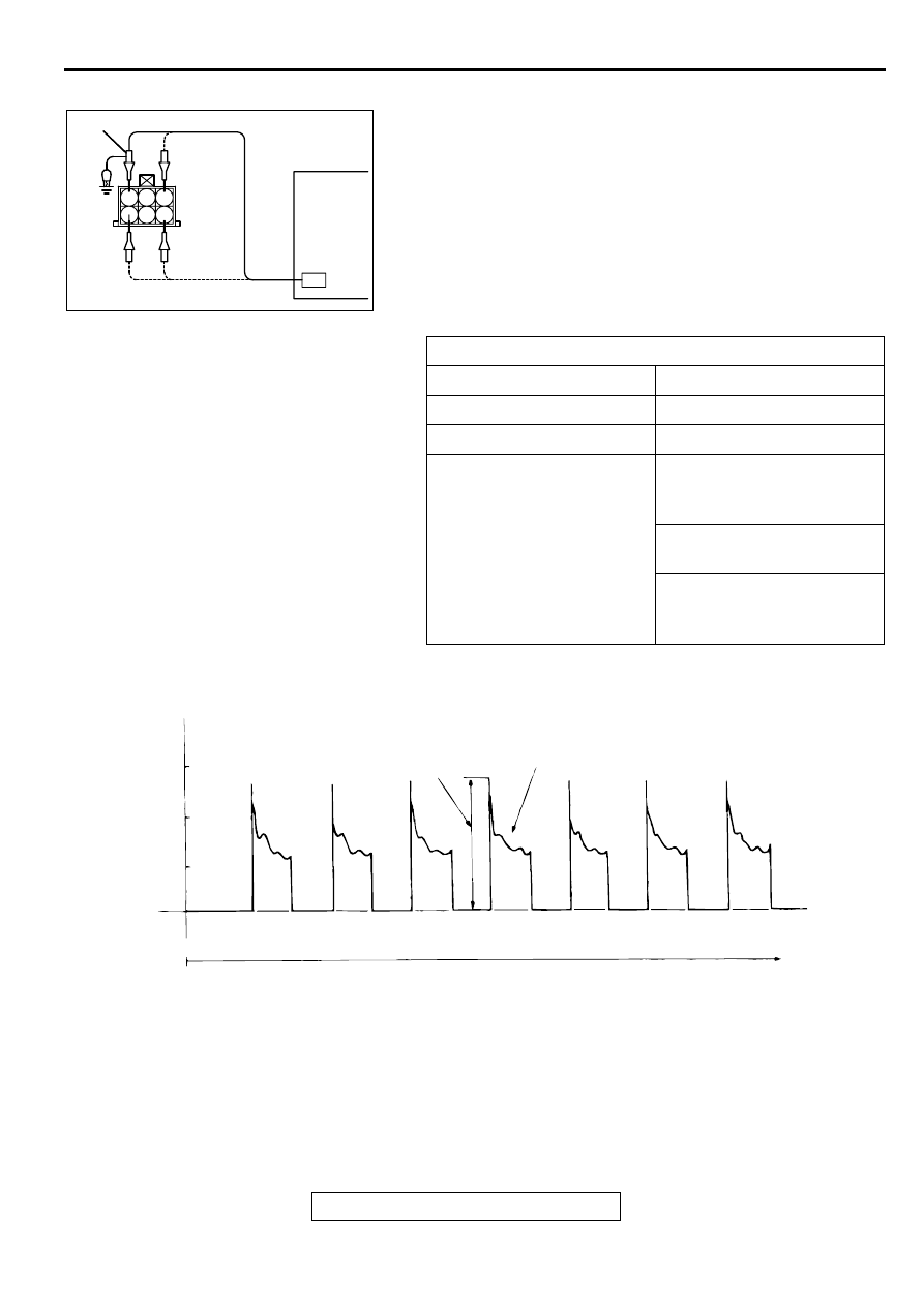
Standard Wave Pattern
Wave Pattern Observation Points
1. Check that the standard wave pattern appears when the
idle air control motor is operating.
Point A:
Presence or absence of induced electromotive force from the
motor turning. (Refer to abnormal wave pattern.)
Observation conditions
Function
Special pattern
Pattern height
High
Pattern selector
Display
Engine condition
Turn the ignition switch from
"OFF" to "ON" (without
starting the engine).
While the engine is idling,
turn the A/C switch to "ON."
Immediately after starting the
warm the engine
(approximately one minute).
AKX01606
6
3
1 2
4 5
OSCILLOSCOPE
OSCILLOSCOPE PLOBE
AKX01606AB
AKX01607 AB
(V)
30
20
10
0
IAC
MOTOR
CONTROL
SIGNAL
WAVE
PATTERN
THE WAVE PATTERN
APPEARS FOR AN
INSTANT, BUT SOON
DISAPPEARS.
POINT B COIL RE-
VERSE ELECTRO-
MOTIVE FORCE
(APPROXIMATELY
3 x10 V)
POINT AN INDUCED
ELECTROMOTIVE
FORCE FROM THE
MOTOR TURNING
TIME
Standard wave pattern
MULTIPORT FUEL INJECTION (MFI) DIAGNOSIS
TSB Revision
MULTIPORT FUEL INJECTION (MFI) <2.4L ENGINE>
13A-464
Point B:
Height of coil back electromotive force
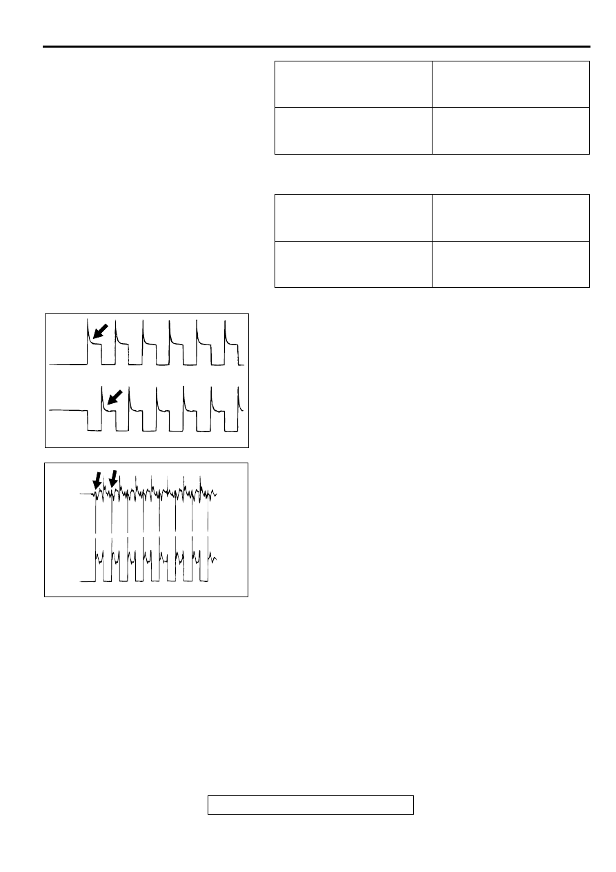
Examples of Abnormal Wave Patterns
Example 1
•
Cause of problem
Malfunction of motor. (Motor is not operating.)
•
Wave pattern characteristics
Induced electromotive force from the motor turning does not
appear.
Example 2
•
Cause of problem
Open circuit in the line between the idle air control motor
and the ECM <M/T> or PCM <A/T>.
•
Wave pattern characteristics
Current is not supplied to the motor coil on the open circuit
side. (Voltage does not drop to 0 volt.) Furthermore, the
induced electromotive force wave pattern at the normal side
is slightly different from the normal wave pattern.
IGNITION COIL AND IGNITION POWER
TRANSISTOR
Required Special Tool:
MB991348: Test Harness Set
CONTRAST WITH
STANDARD WAVE
PATTERN
PROBABLE CAUSE
Induced electromotive force
does not appear or is
extremely small
Malfunction of motor
CONTRAST WITH
STANDARD WAVE
PATTERN
PROBABLE CAUSE
Coil reverse electromotive
force does not appear or is
extremely small
Short in the coil
AKX01608 AB
AKX01609
OPEN
CIRCUIT
SIDE
NORMAL
SIDE
AB
MULTIPORT FUEL INJECTION (MFI) DIAGNOSIS
TSB Revision
MULTIPORT FUEL INJECTION (MFI) <2.4L ENGINE>
13A-465
Measurement Method
1. Disconnect the connector, and connect test harness special
tool, (MB991348), in between. (All terminals should be
connected.)
2. Connect the oscilloscope probe to ignition coil connector
terminal 3.
Alternate method (Test harness not available)
1. Connect the oscilloscope probe to ECM <M/T> or PCM <A/
T> terminal 11.
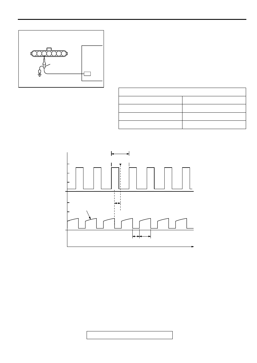
Standard Wave Pattern
Wave Pattern Observation Points
Point: Condition of wave pattern build-up section and maximum
voltage (Refer to abnormal wave pattern examples 1 and 2.
Observation conditions
Function
Special pattern
Pattern height
Low
Pattern selector
Display
Engine r/min
Approximately 1,200 r/min
AK000067
1 2 3 4 5 6 7
OSCILLOSCOPE
DISTRIBUTOR
CONNECTOR
OSCILLO
SCOPE
PLOBE
AB
AK000069
CRANKSHAFT
POSITION
SENSOR OUTPUT
WAVE PATTERN
(REFERENCE)
IGNITION POWER
TRANSISTOR
CONTROL SIGNAL
WAVE PATTERN
POINT:
WAVE BUILD-UP
SECTION
Standard wave pattern
θ
θ
: SPARK ADVANCE ANGLE
ON
DWELL SECTION
TIME
OFF
T
T : CRANKSHAFT ANGLE (120˚)
COMPRESSION
TOP DEAD CENTER
0
2
4
6
0
2
4
6
(V)
MULTIPORT FUEL INJECTION (MFI) DIAGNOSIS
TSB Revision
MULTIPORT FUEL INJECTION (MFI) <2.4L ENGINE>
13A-466
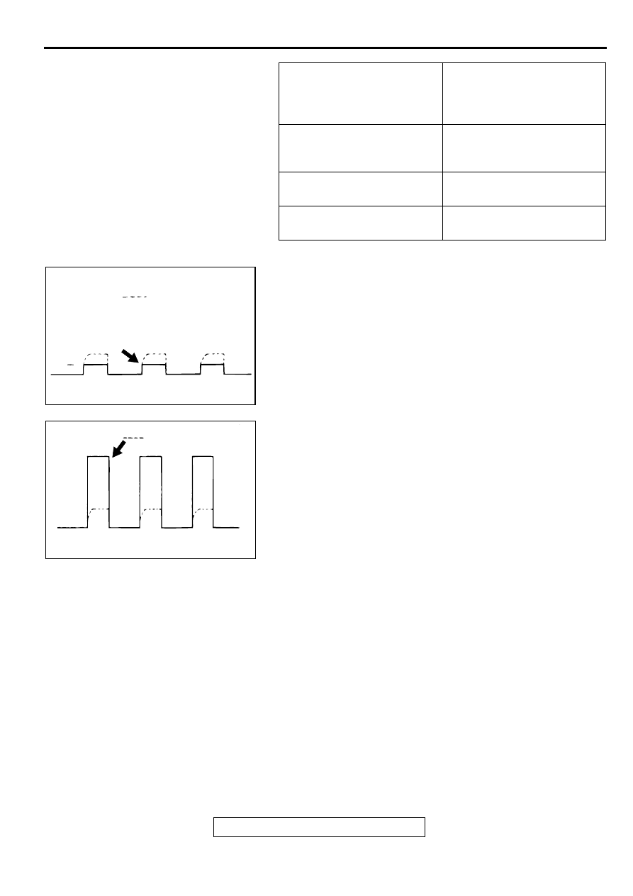
Examples of Abnormal Wave Patterns
Example 1 (Wave pattern during engine cranking)
•
Cause of problem
Open-circuit in ignition primary circuit
•
Wave pattern characteristics
Top-right part of the build-up section cannot be seen, and
voltage value is approximately 2 volts too low.
Example 2 (Wave pattern during engine cranking)
•
Cause of problem
Malfunction in ignition power transistor
•
Wave pattern characteristics
Power voltage results when the ignition power transistor is
ON.
CONDITION OF WAVE
PATTERN BUILD-UP
SECTION AND MAXIMUM
VOLTAGE
PROBABLE CAUSE
Rises from approximate 2
volts to approximate 4.5 volts
at the top-right
Normal
2-volt rectangular wave
Open-circuit in ignition primary
circuit
Rectangular wave at power
voltage
Ignition power transistor
malfunction
AKX01612
NORMAL WAVE
PATTERN
2V
AB
AKX01613
BATTERY
POSITION
VOLTAGE
NORMAL WAVE
PATTERN
AB
Нет комментариевНе стесняйтесь поделиться с нами вашим ценным мнением.
Текст