Mitsubishi Eclipse / Eclipse Spyder (2000-2002). Service and repair manual — part 189

MULTIPORT FUEL INJECTION (MFI) DIAGNOSIS
TSB Revision
MULTIPORT FUEL INJECTION (MFI) <2.4L ENGINE>
13A-455
8478
Throttle position
sensor
Ignition switch:
"ON" (check for
smooth voltage
increase as
throttle is moved
from idle position
to wide open
throttle)
Idle
0.535
−
0.735 V
Wide open throttle
4.5
−
5.5 V
85
55
Barometric
pressure sensor
Ignition switch:
"ON"
When altitude is 0 m (0 ft) 3.7
−
4.3 V
When altitude is 600 m
(1,969 ft)
3.4
−
4.0 V
When altitude is 1,200 m
(3,937 ft)
3.2
−
3.8 V
When altitude is 1,800 m
(5,906 ft)
2.9
−
3.5 V
86
80
Vehicle speed
sensor
•
Ignition switch: "ON"
•
Move the vehicle slowly forward
0
⇔
8 -12 V
(changes
repeatedly)
87
79
Idle position signal Ignition switch:
"ON"
Set throttle valve to idle
position
0
−
1 V
Open throttle slightly
4 V or more
88
56
Camshaft position
sensor
Engine: cranking
0.4
−
3.0 V
Engine: idling
1.5
−
3.0 V
89
45
Crankshaft
position sensor
Engine: cranking
0.4
−
4.0 V
Engine: idling
1.5
−
2.5 V
90
65
Volume air flow
sensor
Engine: idling
2.2
−
3.2 V
Engine: 2,500 r/min
TERMINAL
NO. <M/T>
TERMINAL
NO. <A/T>
INSPECTION ITEM
INSPECTION CONDITION (ENGINE CONDITION)
NORMAL
CONDITION

MULTIPORT FUEL INJECTION (MFI) DIAGNOSIS
TSB Revision
MULTIPORT FUEL INJECTION (MFI) <2.4L ENGINE>
13A-456
TERMINAL RESISTANCE AND CONTINUITY CHECK
AK000058
ECM <M/T> or PCM <A/T> Connector Terminal Arrangement
AB
<M/T>
<A/T>
13 12 11 10
9
8
7
6
5
4
3
2
1
26 25 24 23 22 21 20 19
38 37 36
35 34
33 32 31
35 34 33 32 31
46 45 44 43 42 41
56 55 54 53 52 51
62 61 60 59 58
75 74 73 72 71
80
81
79 78 77 76
86 85 84 83 82
91
92
90 89 88 87
57
40 39
18 17 16 15 14
13 12 11 10
9
8
7
6
5
4
3
2
1
26
27
28
29
30
25
24
23
58
59
60
61
62
63
64
65
66
41
42
43
44
45
46
47
48
49
50
51
52
53
54
55
56
57
90
91
92
93
94
95
96
97
98
71
72
73
74
75
76
77
78
79
80
81
82
83
84
85
86
87
88
89
101
102
103
104
105
106
107
108
121
122
123
124
125
126
127
128
129
130
109
110
111
112
113
114
115
116
117
118
119
120
22 21 20 19 18 17 16
14
15
TERMINAL
NO.
TERMINAL
NO.
INSPECTION ITEM
NORMAL CONDITION (INSPECTION
CONDITION)
1
−
12
1
−
41
No.1 injector
13
−
16
Ω
[at 20
°
C (68
°
F)]
14
−
12
9
−
41
No.2 injector
2
−
12
24
−
41
No.3 injector
15
−
12
2
−
41
No.4 injector
4
−
12
14
−
41
Stepper motor coil (A1)
28
−
33
Ω
[at 20
°
C (68
°
F)]
17
−
12
28
−
41
Stepper motor coil (A2)
5
−
12
15
−
41
Stepper motor coil (B1)
18
−
12
29
−
41
Stepper motor coil (B2)
6
−
12
6
−
41
EGR solenoid
29
−
35
Ω
[at 20
°
C (68
°
F)]
9
−
12
34
−
41
Evaporative emission purge
solenoid
30
−
34
Ω
[at 20
°
C (68
°
F)]
13
−
Body
ground
42
−
Body
ground
ECM or PCM ground
Continuity (0
Ω
)
26
−
Body
ground
48
−
Body
ground
ECM or PCM ground
54
−
12
26
−
41
Heated oxygen sensor heater (rear) 11
−
18
Ω
[at 20
°
C (68
°
F)]
55
−
12
35
−
41
Evaporative emission ventilation
solenoid
17
−
21
Ω
[at 20
°
C (68
°
F)]
60
−
12
3
−
41
Heated oxygen sensor heater
(front)
4.5
−
8.0
Ω
[at 20
°
C (68
°
F)]
72
−
92
57
−
64Intake air temperature sensor
5.3
−
6.7 k
Ω
[when intake air temperature
is 0
°
C (32
°
F)]
2.3
−
3.0 k
Ω
[when intake air temperature
is 20
°
C (68
°
F)]
1.0
−
1.5 k
Ω
[when intake air temperature
is 40
°
C (104
°
F)]
0.30
−
0.42 k
Ω
[when intake air
temperature is 80
°
C (176
°
F)]
MULTIPORT FUEL INJECTION (MFI) DIAGNOSIS
TSB Revision
MULTIPORT FUEL INJECTION (MFI) <2.4L ENGINE>
13A-457
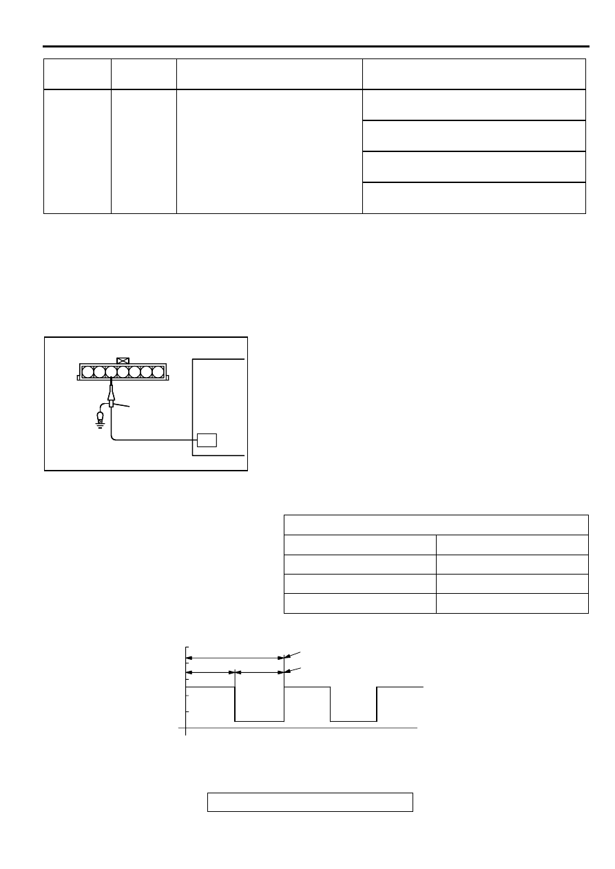
INSPECTION PROCEDURE USING AN
OSCILLOSCOPE
M1131009300166
VOLUME AIR FLOW SENSOR
Required Special Tool:
MB991709: Test Harness
Measurement Method
1. Disconnect the volume air flow sensor connector, and
connect the test harness special tool (MB991709) in
between. (All terminals should be connected.)
2. Connect the oscilloscope probe to volume air flow sensor
connector terminal 3.
Alternate method (Test harness not available)
<M/T>
1. Connect the oscilloscope probe to ECM terminal 61.
<A/T>
1. Connect the oscilloscope probe to PCM terminal 65.
Standard Wave Pattern
83
−
92
44
−
57
Engine coolant temperature sensor 5.1
−
6.5 k
Ω
[when engine coolant
temperature is 0
°
C (32
°
F)]
2.1
−
2.7 k
Ω
[when engine coolant
temperature is 20
°
C (68
°
F)]
0.9
−
1.3 k
Ω
[when engine coolant
temperature is 40
°
C (104
°
F)]
0.26
−
0.36 k
Ω
[when engine coolant
temperature is 80
°
C (176
°
F)]
TERMINAL
NO.
TERMINAL
NO.
INSPECTION ITEM
NORMAL CONDITION (INSPECTION
CONDITION)
Observation conditions
Function
Special pattern
Pattern height
Low
Pattern selector
Display
Engine r/min
Idle speed
AKX01594
OSCILLOSCOPE
OSCILLOSCOPE
PLOBE
4 5 6
1 2 3
7
AKX01594AB
AKX01595
THE TIME (CYCLE TIME) T IS REDUCED WHEN THE
AMOUNT OF INTAKE AIR INCREASES.
TIMES T
1
AND T
2
ARE EQUAL
T
T
1
T
2
10
0
(V)
TIME
AB
Standard wave pattern
MULTIPORT FUEL INJECTION (MFI) DIAGNOSIS
TSB Revision
MULTIPORT FUEL INJECTION (MFI) <2.4L ENGINE>
13A-458
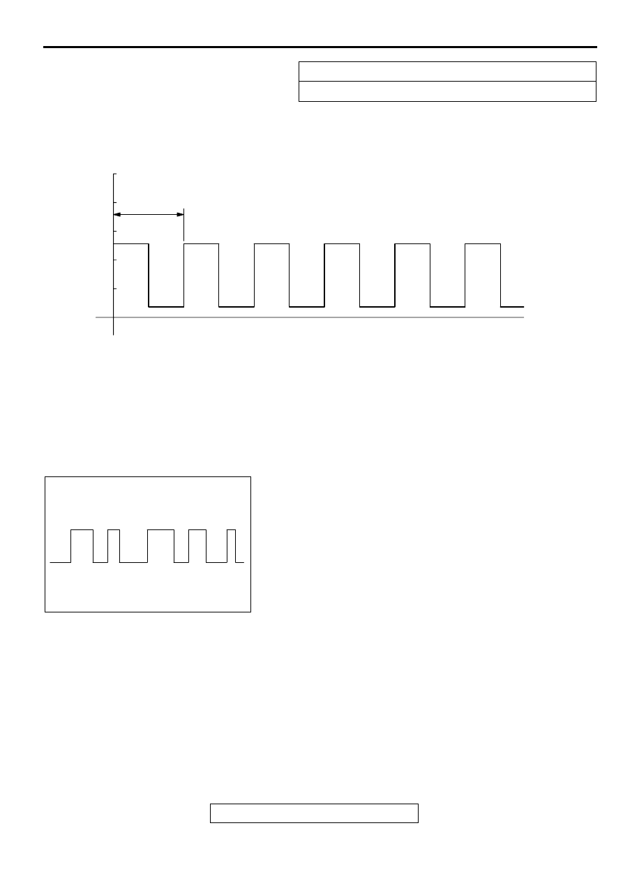
Wave Pattern Observation Points
1. Check that cycle time T becomes shorter and the frequency
increases when the engine speed is increased.
Examples of Abnormal Wave Patterns
Example 1
•
Cause of problem
Sensor interface malfunction.
•
Wave pattern characteristics
Rectangular wave pattern is output even when the engine is
not started.
Example 2
•
Cause of problem
Damaged rectifier or vortex generation column.
•
Wave pattern characteristics
Unstable wave pattern with non-uniform frequency. An
ignition leak will distort the wave pattern temporarily, even if
the volume air flow sensor is normal.
Observation conditions
Rev engine, observe T1 and T2 remain equal.
AKX01596
10
0
(V)
T
TIME
AB
Standard wave pattern
AKX01597
Нет комментариевНе стесняйтесь поделиться с нами вашим ценным мнением.
Текст