Mitsubishi Eclipse / Eclipse Spyder (2000-2002). Service and repair manual — part 161
MULTIPORT FUEL INJECTION (MFI) DIAGNOSIS
TSB Revision
MULTIPORT FUEL INJECTION (MFI) <2.4L ENGINE>
13A-343
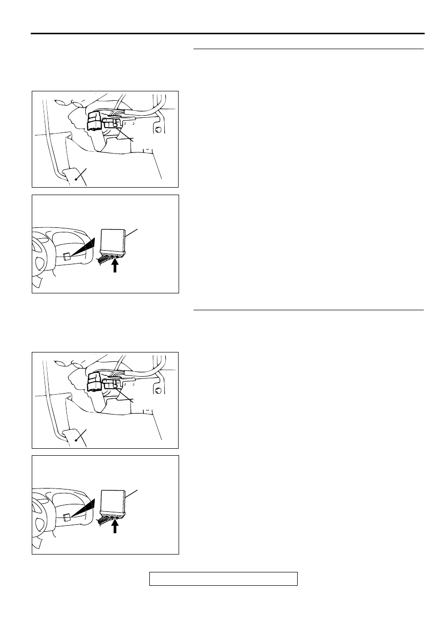
STEP 2. Check for open circuit, short circuit to ground and
harness damage between data link connector C-29
terminal 1 and ECM connector C-56 terminal 56 <M/T> or
PCM connector C-57 terminal 84 <A/T>.
NOTE: Check harness after checking intermediate connectors
C-77 and C-28. If intermediate connectors are damaged, repair
or replace them. Refer to GROUP 00E, Harness Connector
Inspection (
). Then check that the malfunction is
eliminated.
Q: Is the harness wire in good condition?
YES : Go to Step 3.
NO : Repair it. Then confirm that the malfunction symptom
is eliminated.
STEP 3. Check for open circuit, short circuit to ground and
harness damage between data link connector C-29
terminal 7 and ECM connector C-56 terminal 62 <M/T> or
PCM connector C-57 terminal 85 <A/T>.
NOTE: Check harness after checking intermediate connectors
C-77 and C-28. If intermediate connectors are damaged, repair
or replace them. Refer to GROUP 00E, Harness Connector
Inspection (
). Then check that the malfunction is
eliminated.
Q: Is the harness wire in good condition?
YES : Refer to, INSPECTION PROCEDURE 29
−
Power
Supply System and Ignition Switch-IG System(
NO : Repair it. Then confirm that the malfunction symptom
is eliminated.
ACX02447
CONNECTOR:C-29
ACCELERATOR
PEDAL
DATA LINK
CONNECTOR
AI
AK000280
C-56,C-57
ECM<M/T>
OR
PCM<A/T>
CONNECTORS:C-56<M/T>,C-57<A/T>
BJ
ACX02447
CONNECTOR:C-29
ACCELERATOR
PEDAL
DATA LINK
CONNECTOR
AI
AK000280
C-56,C-57
ECM<M/T>
OR
PCM<A/T>
CONNECTORS:C-56<M/T>,C-57<A/T>
BJ
MULTIPORT FUEL INJECTION (MFI) DIAGNOSIS
TSB Revision
MULTIPORT FUEL INJECTION (MFI) <2.4L ENGINE>
13A-344
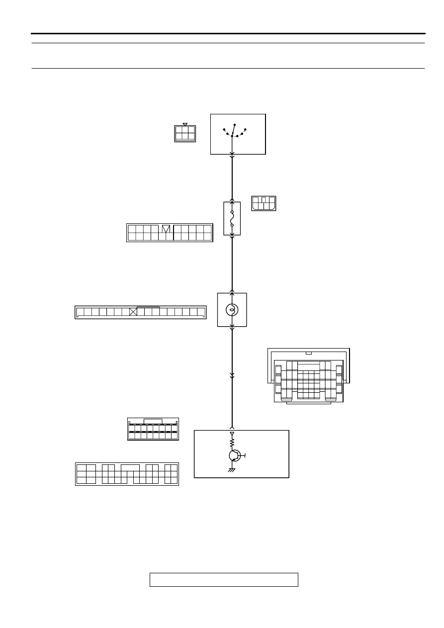
INSPECTION PROCEDURE 3: The Service Engine Soon/Malfunction Indicator Lamp Does Not
Illuminate Right after the Ignition Switch Is Turned to the "ON" Position.
AK000675
44 45
41
46 47
42 43
49 50 5152
48
55 56
54
53
3
2
4 5 6
1 2 3
4 5 6
GREEN
1
RED-
YELLO
W
RED-
YELLO
W
BLA
CK-
WHITE
C-104
(MU801457)
R
IG2
ST
LOCK
ACC
IG1
C-101
MU801331
IGNITION
SWITCH
C-87
2
6
6
JUNCTION
BLOCK
52
C-41
41
C-28
SERVICE ENGINE SOON/
MALFUNCTION
INDICATOR LAMP
C-53<M/T>
(MU803771)
C-50<A/T>
(MU803784)
ENGINE CONTROL
MODULE(ECM)<M/T>
OR
POWERTRAIN CONTROL
MODULE(PCM)<A/T>
21
36<M/T>
22<A/T>
1
6
4
5
11
10
12 13
15
17
16
14
19
18
8 9
7
20
2 3
7 8
5
3 4
35
34
10 11 12
2122 23 24
13 14 15
25 26 27
16
28
17
18 19 20
29
30 31
32 33
36 37
38
9
1 2
6
34
33
32
36
35
37
42
45
31
39
38
46
40 41
43 44
2
3 4
5 6
7 8
9
11 12 13 14 15 16 17 18 19 20
30
21 22 23
24 25
26 27 28 29
3132 33
34 35
1
10
MULTIPORT FUEL INJECTION (MFI) DIAGNOSIS
TSB Revision
MULTIPORT FUEL INJECTION (MFI) <2.4L ENGINE>
13A-345
CIRCUIT OPERATION
•
The service engine soon/malfunction indicator
lamp power is supplied from the ignition switch.
•
The ECM <M/T> or PCM <A/T> controls the
ground of the service engine soon/malfunction
indicator lamp by turning the power transistor in
the ECM <M/T> or PCM <A/T> ON and OFF.
COMMENT
•
The ECM <M/T> or PCM <A/T> causes the
service engine soon/malfunction indicator lamp to
illuminate for 5 seconds immediately after the
ignition switch is turned to the "ON" position
occurred.
TROUBLESHOOTING HINTS (The most likely
causes for this case:)
•
Burnt-out bulb.
•
Defective service engine soon/malfunction
indicator lamp circuit.
•
Malfunction of the ECM <M/T> or PCM <A/T>.
DIAGNOSIS
Required Special Tool:
MB991502:Scan Tool (MUT-II)
AK000312AI
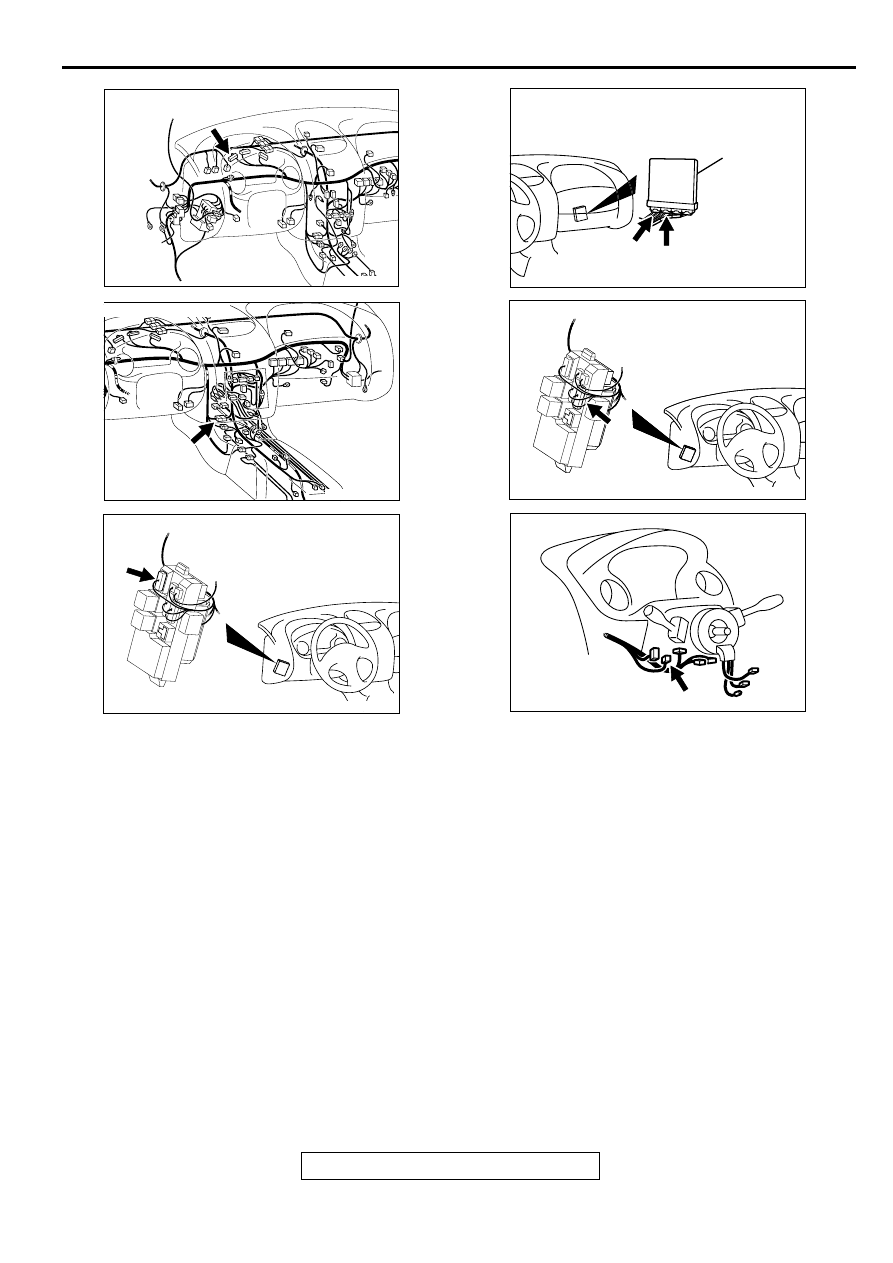
CONNECTOR:C-41
AK000733AC
CONNECTOR:C-28
AK000315
CONNECTOR:C-101
AC
AK000280
C-50
C-53
ECM<M/T>
OR
PCM<A/T>
CONNECTORS:C-53<M/T>,C-50<A/T>
BK
AK000311
AK000311
CONNECTOR:C-104
AC
AK000219
CONNECTOR:C-87
AC
MULTIPORT FUEL INJECTION (MFI) DIAGNOSIS
TSB Revision
MULTIPORT FUEL INJECTION (MFI) <2.4L ENGINE>
13A-346
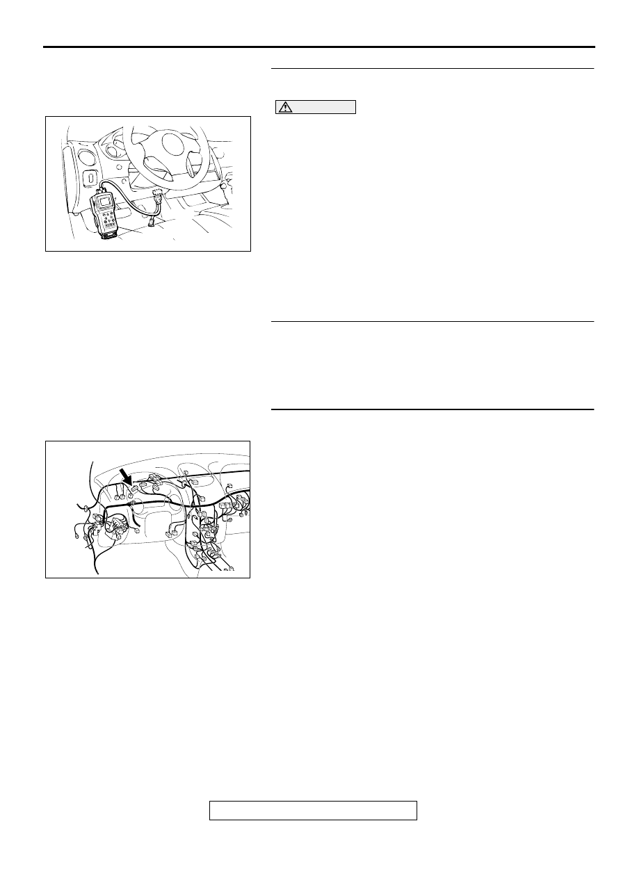
STEP 1. Using scan tool MB991502, check data list item 16:
Power Supply Voltage.
CAUTION
To prevent damage to scan tool MB991502, always turn the
ignition switch to the "LOCK" (OFF) position before.
connecting or disconnecting scan tool MB991502.
(1) Connect scan tool MB991502 to the data link connector.
(2) Turn the ignition switch to the "ON" position.
(3) Set scan tool MB991502 to the data reading mode for item
16, Power Supply Voltage.
•
Voltage should be battery positive voltage.
(4) Turn the ignition switch to the "LOCK" (OFF) position.
Q: Is the voltage normal?
YES : Go to Step 2.
NO : Refer to INSPECTION PROCEDURE 29
−
Power
Supply System and Ignition Switch-IG System
(
).
STEP 2. Check the burned-out bulb.
Q: Is the valve normal?
YES : Go to step 3.
NO : Replace the bulb. Then confirm that the malfunction
symptom is eliminated.
STEP 3. Check connector C-41 at the combination meter
for damage.
Q: Is the connector in good condition?
YES : Go to step 4.
NO : Repair or replace it. Refer to GROUP 00E, Harness
Connector Inspection (
). Then confirm that
the malfunction symptom is eliminated.
AKX01177
16 PIN
MB991502
AB
AK000312AI
CONNECTOR:C-41
Нет комментариевНе стесняйтесь поделиться с нами вашим ценным мнением.
Текст