Mitsubishi Eclipse / Eclipse Spyder (2000-2002). Service and repair manual — part 146
MULTIPORT FUEL INJECTION (MFI) DIAGNOSIS
TSB Revision
MULTIPORT FUEL INJECTION (MFI) <2.4L ENGINE>
13A-283
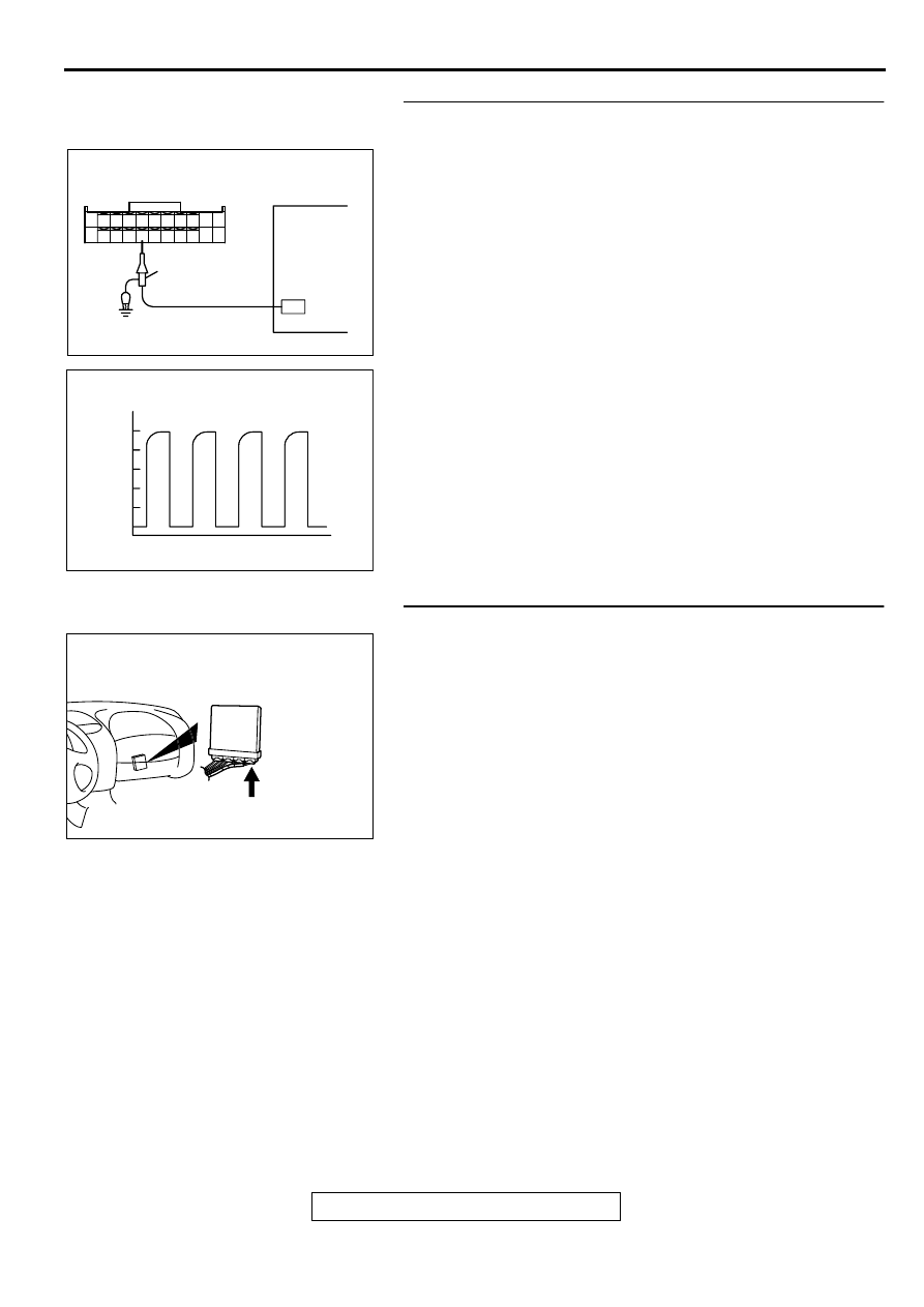
STEP 3. Using the oscilloscope, check the sensor output
voltage at ECM connector C-60.
(1) Do not disconnect the ECM connector C-60.
(2) Disconnect the combination meter connector and auto-
cruise control-ECU connector.
(3) Connect the oscilloscope probe to ECM terminal 86 by
backprobing.
(4) Start the engine.
(5) Check the waveform.
•
The waveform should show a pattern similar to the
illustration while the vehicle is being moved.
(6) Turn the ignition switch to the "LOCK" (OFF) position.
Q: Is the waveform normal?
YES : Go to Step 4.
NO : Go to Step 6.
STEP 4. Check connector C-60 at ECM for damage.
Q: Is the connector in good condition?
YES : Go to Step 5.
NO : Repair or replace it. Refer to GROUP 00E, Harness
Connector Inspection (
). Then go to Step 17.
AK000324
ECM CONNECTOR
OSCILLOSCOPE
OSCILLOSCOPE
PLOBE
7172 73 74 75 76 77 78 79 80 81
82 83 84 85 86 87 88 89 90 9192
AB
AKX01562
AKX01562
(ms)
0
(V)
NORMAL WAVEFORM
AB
AK000280
CONNECTOR:C-60
BI
MULTIPORT FUEL INJECTION (MFI) DIAGNOSIS
TSB Revision
MULTIPORT FUEL INJECTION (MFI) <2.4L ENGINE>
13A-284
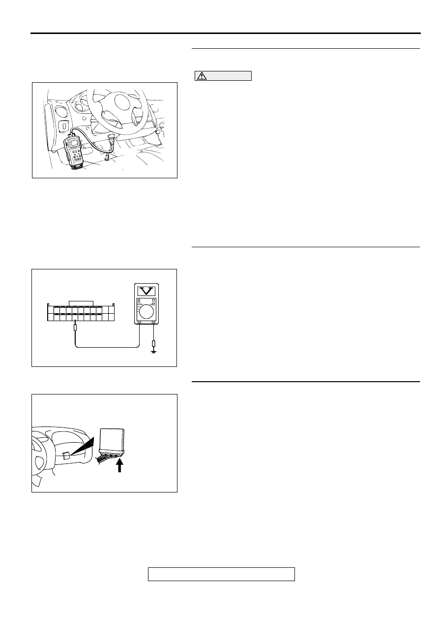
STEP 5. Using scan tool MB991502, check data list item 24:
Vehicle Speed Sensor.
CAUTION
To prevent damage to scan tool MB991502, always turn the
ignition switch to the "LOCK" (OFF) position before
connecting or disconnecting scan tool MB991502.
(1) Connect scan tool MB991502 to the data link connector.
(2) Start the engine.
(3) Set scan tool MB991502 to the data reading mode for item
24, Vehicle Speed Sensor.
•
Check that the speedometer and MUT-II display speed
match when traveling at a vehicle speed of 40km/h
(25mph).
(4) Turn the ignition switch to the "LOCK" (OFF) position.
Q: Is the sensor operating properly?
YES : It can be assumed that this malfunction is intermittent.
Refer to GROUP 00, How to Use Troubleshooting/
Inspection Service Points (
NO : Replace the ECM. Then go to Step 17.
STEP 6. Check the sensor supply voltage at ECM
connector C-60 by backprobing
(1) Do not disconnect the ECM connector C-60.
(2) Disconnect the vehicle speed sensor connector B-39.
(3) Turn the ignition switch to the "ON" position.
(4) Measure the voltage between terminal 86 and ground by
backprobing.
•
Voltage should be between 4.8 and 5.2 volts.
(5) Turn the ignition switch to the "LOCK" (OFF) position.
Q: Is the voltage normal?
YES : Go to Step 7.
NO : Replace the ECM. Then go to Step 17.
STEP 7. Check connector C-60 at ECM for damage.
Q: Is the connector in good condition?
YES : Check connector B-36 at intermediate connector for
damage, and repair or replace as required. Refer to
GROUP 00E, Harness Connector Inspection (
). If intermediate connector is in good condition,
repair harness wire between vehicle speed sensor
connector B-39 terminal 3 and ECM connector C-60
terminal 86 because of open circuit. Then go to Step
17.
NO : Repair or replace it. Refer to GROUP 00E, Harness
Connector Inspection (
). Then go to Step 17.
AKX01177
16 PIN
MB991502
AB
AK000304
7172 73 74 75 76 77 78 79 80 81
82 83 84 85 86 87 88 89 90
92
91
AC
C-60 CONNECTOR
HARNESS SIDE VIEW
AK000280
CONNECTOR:C-60
BI
MULTIPORT FUEL INJECTION (MFI) DIAGNOSIS
TSB Revision
MULTIPORT FUEL INJECTION (MFI) <2.4L ENGINE>
13A-285
STEP 8. Check connector B-39 at vehicle speed sensor for
damage.
Q: Is the connector in good condition?
YES : Go to Step 9.
NO : Repair or replace it. Refer to GROUP 00E, Harness
Connector Inspection (
). Then go to Step 17.
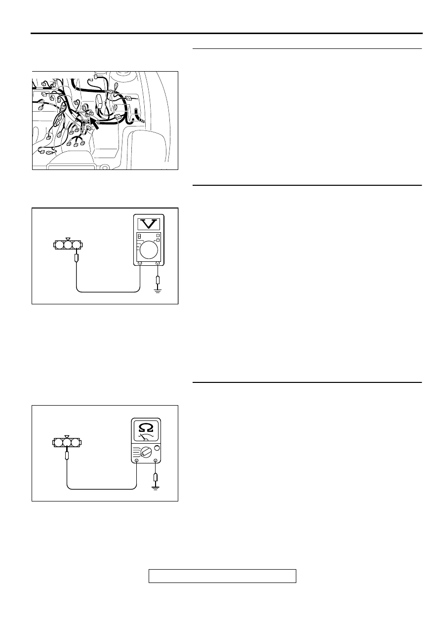
STEP 9. Check the power supply voltage at vehicle speed
sensor harness side connector B-39.
(1) Disconnect the connector B-39 and measure at the harness
side.
(2) Turn the ignition switch to the "ON" position.
(3) Measure the voltage between terminal 1 and ground.
•
Voltage should be battery positive voltage.
(4) Turn the ignition switch to the "LOCK" (OFF) position.
Q: Is the voltage normal?
YES : Go to Step 10.
NO : Check connectors B-36, C-28, C-78, C-104 and C-
101 at intermediate connector for damage, and repair
or replace as required. Refer to GROUP 00E,
Harness Connector Inspection (
). If
intermediate connectors are in good condition, repair
harness wire between ignition switch connector C-87
terminal 2 and vehicle speed sensor connector B-39
terminal 1 because of open circuit or short circuit to
ground. Then go to Step 17.
STEP 10. Check the continuity at vehicle speed sensor
harness side connector B-39.
(1) Disconnect the connector B-39 and measure at the harness
side.
(2) Check for the continuity between terminal 2 and ground.
•
Should be less than 2 ohm.
Q: Is the continuity normal?
YES : Go to Step 11.
NO : Check connector B-36 at intermediate connector for
damage, and repair or replace as required. Refer to
GROUP 00E, Harness Connector Inspection (
). If intermediate connector is in good condition,
repair harness wire between vehicle speed sensor
connector B-39 terminal 2 and ground because of
open circuit or harness damage. Then go to Step 17.
AK000547AC
CONNECTOR:B-39
AKX01425AD
1
2
3
B-39 HARNESS
SIDE CONNECTOR
AKX01426AD
1
2
3
B-39 HARNESS
SIDE CONNECTOR
MULTIPORT FUEL INJECTION (MFI) DIAGNOSIS
TSB Revision
MULTIPORT FUEL INJECTION (MFI) <2.4L ENGINE>
13A-286
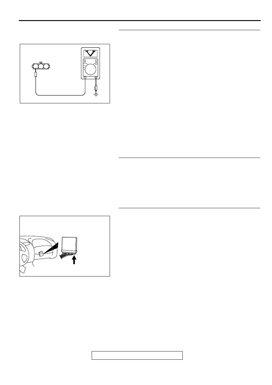
STEP 11. Check the sensor supply voltage at vehicle
speed sensor harness side connector B-39.
(1) Disconnect the vehicle speed sensor connector B-39 and
measure at the harness side.
(2) Disconnect the combination meter connector and auto-
cruise control-ECU connector.
(3) Turn the ignition switch to the "ON" position.
(4) Measure the voltage between terminal 3 and ground.
•
Voltage should be between 4.8 and 5.2 volts.
(5) Turn the ignition switch to the "LOCK" (OFF) position.
Q: Is the voltage normal?
YES : Go to Step 12.
NO : Check connector B-36 at intermediate connector for
damage, and repair or replace as required. Refer to
GROUP 00E, Harness Connector Inspection (
). If intermediate connector is in good condition,
repair harness wire between vehicle speed sensor
connector B-39 terminal 3 and ECM connector C-60
terminal 86 because of short circuit to ground or
harness damage. Then go to Step 17.
STEP 12. Check the vehicle speed sensor.
Refer to GROUP 54A, Combination Metre
−
Inspection
−
Vehicle Speed Sensor Check (
).
Q: Is the vehicle speed sensor normal?
YES : Go to Step 13.
NO : Replace the vehicle speed sensor. Then go to Step
17.
STEP 13. Check connector C-60 at ECM for damage.
Q: Is the connector in good condition?
YES : Go to Step 14.
NO : Repair or replace it. Refer to GROUP 00E, Harness
Connector Inspection (
). Then go to Step 17.
AKX01427AG
1
2
3
B-39 HARNESS
SIDE CONNECTOR
AK000280
CONNECTOR:C-60
BI
Нет комментариевНе стесняйтесь поделиться с нами вашим ценным мнением.
Текст