Mitsubishi Eclipse / Eclipse Spyder (2000-2002). Service and repair manual — part 209
MULTIPORT FUEL INJECTION (MFI) DIAGNOSIS
TSB Revision
MULTIPORT FUEL INJECTION (MFI) <3.0L ENGINE>
13B-35
CIRCUIT OPERATION
•
The volume air flow sensor power is supplied
from the MFI relay (terminal 1), and the ground is
provided on the ECM (terminal 49) <M/T> or
PCM (terminal 57) <A/T>.
•
5-volt power is applied to the volume air flow
sensor output terminal (terminal 3) from the ECM
(terminal 61) <M/T> or PCM (terminal 65) <A/T>.
The volume air flow sensor generates a pulse
signal when the output terminal and ground are
opened/closed (opened/short).
TECHNICAL DESCRIPTION
•
While the engine is running, the volume air flow
sensor outputs a pulse signal which corresponds
to the volume of air flow.
•
The ECM <M/T> or PCM <A/T> checks whether
the frequency of this signal output by the volume
air flow sensor while the engine is running is at or
above the set value.
•
When the throttle position sensor output voltage
is low, the ECM <M/T> or PCM <A/T> causes the
power transistor to be "ON" to send an air flow
sensor reset signal to the air flow sensor. In
response to the reset signal, the air flow sensor
resets the filter circuit and improves the ability of
the air flow sensor to measure the amount of air
in a small air intake region.
DTC SET CONDITIONS
Check Conditions
•
Throttle position sensor voltage is 2 volts or
lower.
•
Engine speed is lower than 2,000 r/min.
Judgement Criteria
•
Volume air flow sensor output frequency has
continued to be 800 Hz or higher for 2 seconds.
TROUBLESHOOTING HINTS (The most likely
causes for this code to be set are:)
•
Volume air flow sensor failed.
•
Open or shorted volume air flow sensor circuit, or
loose connector.
•
ECM failed. <M/T>
•
PCM failed. <A/T>
•
Air leak between volume air flow sensor and
throttle body.
DIAGNOSIS
Required Special Tools
MB991502: Scan Tool (MUT-II)
ACX02480
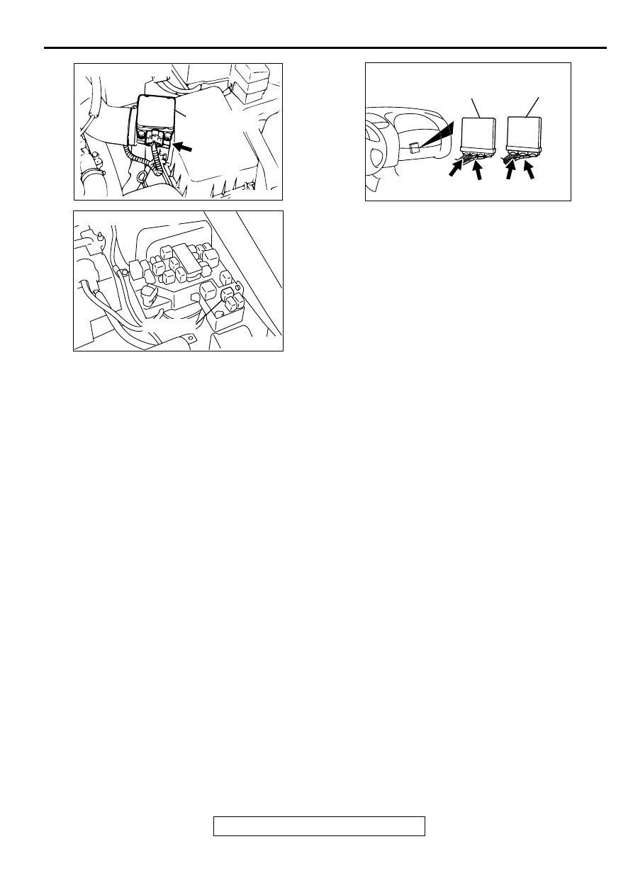
CONNECTOR : B-14
AC
VOLUME AIR
FLOW SENSOR
AK000226
AK000226AB
CONNECTOR : A-21X
MFI RELAY
AK000225
C-52
C-55
C-51
C-58
CONNECTORS:C-51,C-58<M/T>
C-52,C-55<A/T>
ECM<M/T>
PCM<A/T>
AH
MULTIPORT FUEL INJECTION (MFI) DIAGNOSIS
TSB Revision
MULTIPORT FUEL INJECTION (MFI) <3.0L ENGINE>
13B-36
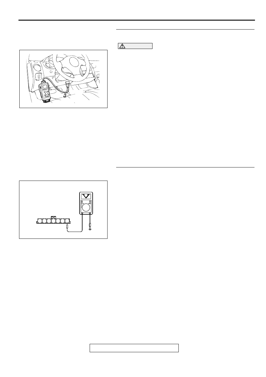
STEP 1. Using scan tool MB991502, check data list item 12:
Volume Air Flow Sensor.
CAUTION
To prevent damage to scan tool MB991502, always turn the
ignition switch to the "LOCK" (OFF) position before
connecting or disconnecting scan tool MB991502.
(1) Connect scan tool MB991502 to the data link connector.
(2) Start the engine and run at idle.
(3) Set scan tool MB991502 to the data reading mode for item
12, Volume Air Flow Sensor.
(4) Warm up the engine to normal operating temperature:80
°
C
to 96
°
C(176
°
F to 205
°
F).
•
The standard value during idling should be 10Hz or
more.
•
When the engine is revved, the frequency should
increase according to the increase in engine speed.
(5) Turn the ignition switch to the "LOCK" (OFF) position.
Q: Is the sensor operating properly?
YES : It can be assumed that this malfunction is intermittent.
Refer to GROUP 00, How to Use Troubleshooting/
Inspection Service Points (
NO : Go to Step 2.
STEP 2. Check the reset signal voltage at volume air flow
sensor connector B-14 by backprobing
(1) Do not disconnect the connector B-14.
(2) Turn the ignition switch to the "ON" position.
(3) Measure the voltage between terminal 7 and ground by
backprobing.
•
Voltage should be between 6.0 and 9.0 volts.
(4) Turn the ignition switch to the "LOCK" (OFF) position.
Q: Is the voltage normal?
YES : Go to Step 5.
NO : Go to Step 3.
AKX01177
16 PIN
MB991502
AB
AKX01515 AC
B-14 CONNECTOR
HARNESS
SIDE VIEW
1 2 3 4 5 6 7
MULTIPORT FUEL INJECTION (MFI) DIAGNOSIS
TSB Revision
MULTIPORT FUEL INJECTION (MFI) <3.0L ENGINE>
13B-37
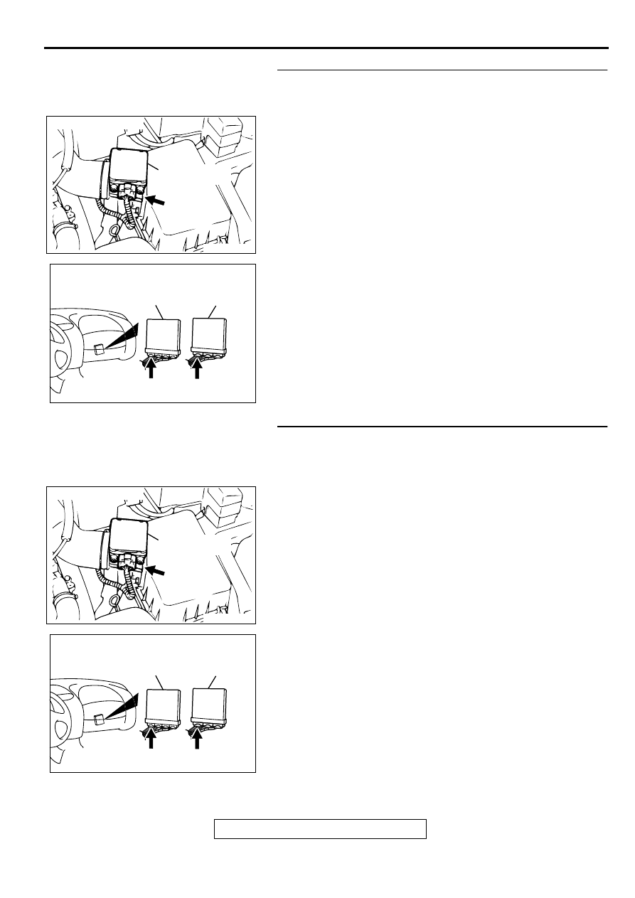
STEP 3. Check connector B-14 at volume air flow sensor
and connector C-51 at ECM <M/T> or connector C-52 at
PCM <A/T> for damage.
Q: Is the connector in good condition?
YES : Go to Step 4.
NO : Repair or replace it. Refer to GROUP 00E, Harness
Connector Inspection (
). Then go to Step 9.
STEP 4. Check for short circuit to ground between volume
air flow sensor connector B-14 terminal 7 and ECM
connector C-51 terminal 19 <M/T> or PCM connector C-52
terminal 19 <A/T>.
Q: Is the harness wire in good condition?
YES : Replace the volume air flow sensor. Then go to Step
9.
NO : Repair it. Then go to Step 9.
ACX02480
CONNECTOR : B-14
AC
VOLUME AIR
FLOW SENSOR
AK000225
CONNECTOR : C-51<M/T>, C-52<A/T>
C-52
C-51
PCM<A/T>
ECM<M/T>
AJ
ACX02480
CONNECTOR : B-14
AC
VOLUME AIR
FLOW SENSOR
AK000225
CONNECTOR : C-51<M/T>, C-52<A/T>
C-52
C-51
PCM<A/T>
ECM<M/T>
AJ
MULTIPORT FUEL INJECTION (MFI) DIAGNOSIS
TSB Revision
MULTIPORT FUEL INJECTION (MFI) <3.0L ENGINE>
13B-38
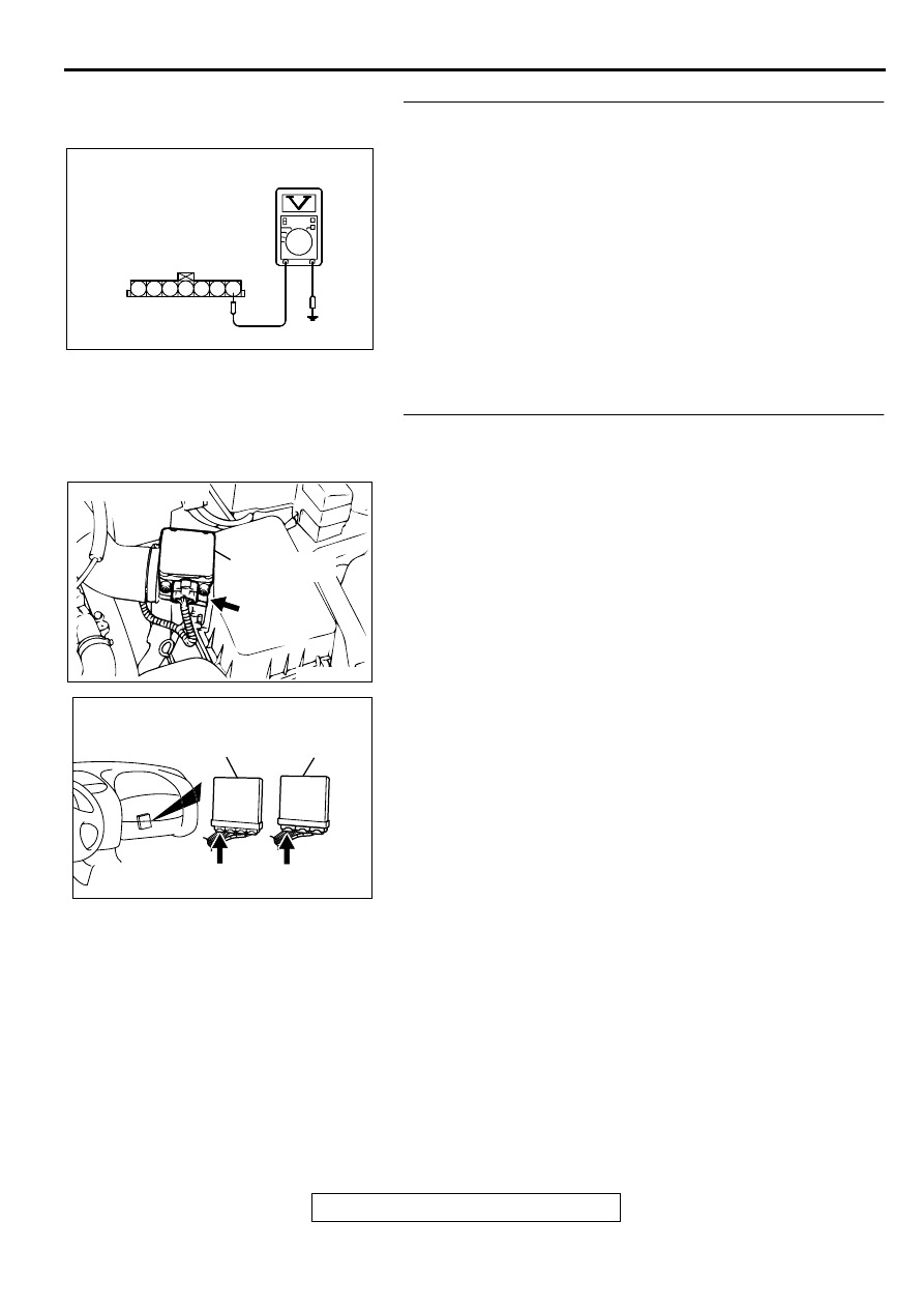
STEP 5. Check the reset signal voltage at volume air flow
sensor connector B-14 by backprobing.
(1) Do not disconnect the connector B-14.
(2) Start the engine and run at idle.
(3) Measure the voltage between terminal 7 and ground by
backprobing.
•
When the engine idling, voltage should be 1.0 volt or
less.
•
When the engine speed is 3000r/min, voltage should be
between 6.0 and 9.0 volts.
(4) Turn the ignition switch to the "LOCK" (OFF) position.
Q: Is the voltage normal?
YES : Go to Step 8.
NO : Go to Step 6.
STEP 6. Check connector B-14 at volume air flow sensor
and connector C-51 at ECM <M/T> or connector C-52 at
PCM <A/T> for damage.
Q: Is the connector in good condition?
YES : Go to Step 7.
NO : Repair or replace it. Refer to GROUP 00E, Harness
Connector Inspection (
). Then go to Step 9.
AKX01515 AC
B-14 CONNECTOR
HARNESS
SIDE VIEW
1 2 3 4 5 6 7
ACX02480
CONNECTOR : B-14
AC
VOLUME AIR
FLOW SENSOR
AK000225
CONNECTOR : C-51<M/T>, C-52<A/T>
C-52
C-51
PCM<A/T>
ECM<M/T>
AJ
Нет комментариевНе стесняйтесь поделиться с нами вашим ценным мнением.
Текст