Mitsubishi Eclipse / Eclipse Spyder (2000-2002). Service and repair manual — part 261
MULTIPORT FUEL INJECTION (MFI) DIAGNOSIS
TSB Revision
MULTIPORT FUEL INJECTION (MFI) <3.0L ENGINE>
13B-243
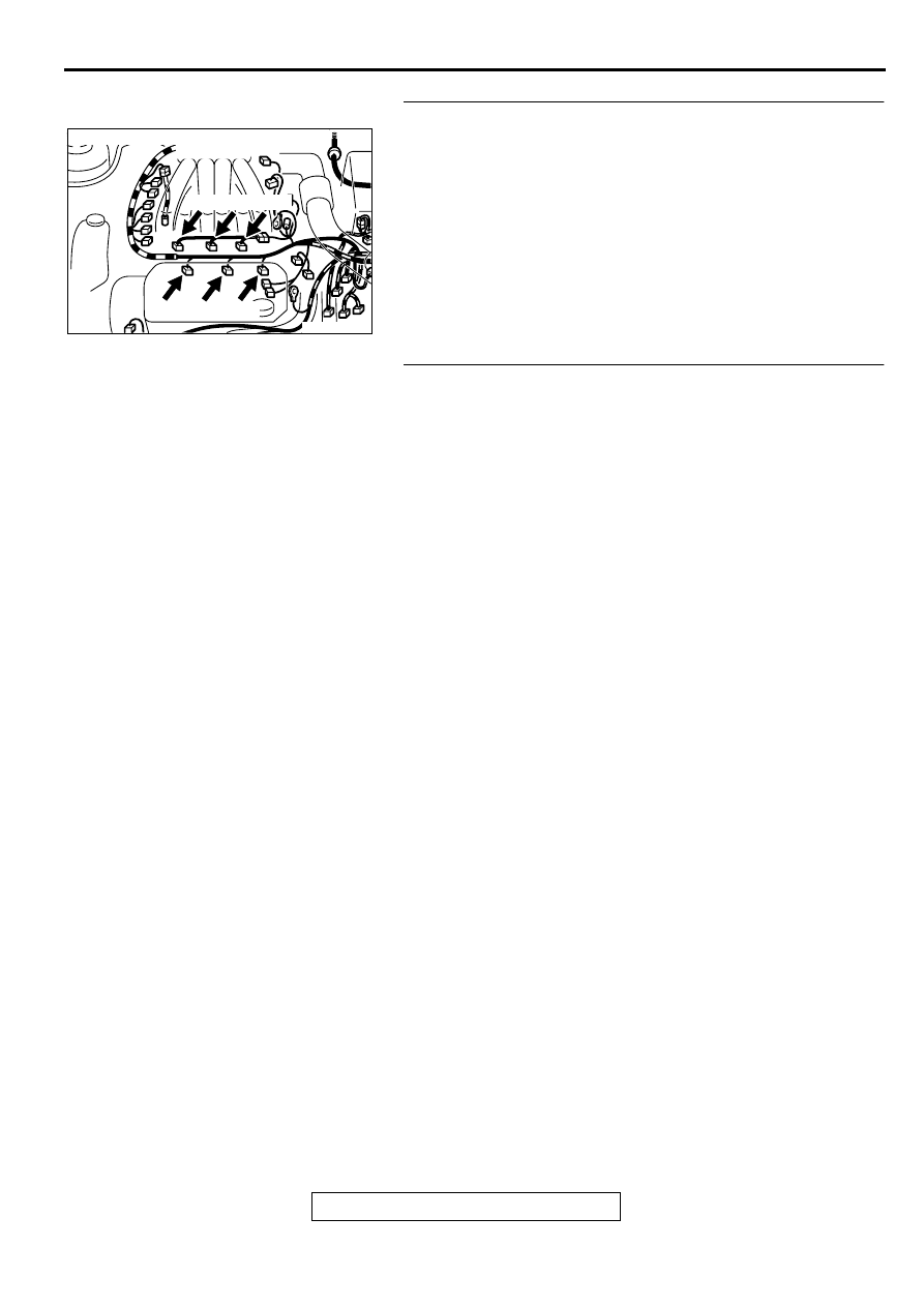
STEP 8. Replace the injector.
(1) Replace the injector.
(2) Carry out a test drive with the drive cycle pattern. Refer to,
Procedure 6
−
Other Monitor (
).
(3) Check the diagnostic trouble code (DTC).
Q: Is the DTC P0301, P0302, P0303, P0304, P0305, P0306 is
output?
YES : Replace the ECM or PCM. Then go to Step 9.
NO : The inspection is complete.
STEP 9. Test the OBD-II drive cycle.
(1) Carry out a test drive with the drive cycle pattern. Refer to,
Procedure 6
−
Other Monitor (
).
(2) Check the diagnostic trouble code (DTC).
Q: Is the DTC P0301, P0302, P0303, P0304, P0305, P0306 is
output?
YES : Retry the troubleshooting.
NO : The inspection is complete.
AK000215
AK000215
B-01 B-05 B-26
B-02 B-06 B-25
AB
CONNECTORS : B-01, B-02, B-05, B-06,
B-25, B-26
MULTIPORT FUEL INJECTION (MFI) DIAGNOSIS
TSB Revision
MULTIPORT FUEL INJECTION (MFI) <3.0L ENGINE>
13B-244
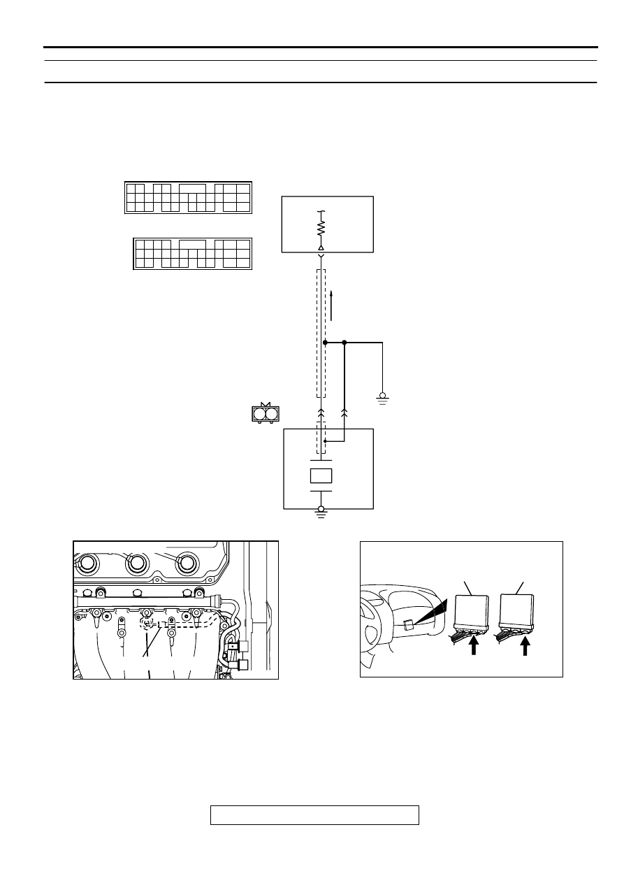
DTC P0325: Knock Sensor 1 Circuit Malfunction
CIRCUIT OPERATION
•
The knock sensor sends a signal voltage to the
ECM (terminal 91) <M/T> or PCM (terminal 90)
<A/T>.
TECHNICAL DESCRIPTION
•
The knock sensor converts the vibration of the
cylinder block into a voltage and outputs it. If
there is a malfunction of the knock sensor, the
voltage output will not change.
•
The ECM <M/T> or PCM <A/T> checks whether
the voltage output changes.
AK000700
1 2
WHITE
BLA
CK
BLA
CK
ENGINE CONTROL
MODULE(ECM)<M/T>
OR
POWERTRAIN CONTROL
MODULE(PCM)<A/T>
91<M/T>
90<A/T>
B-35
MU802661
1
2
KNOCK SENSOR
98
78
71
88 89
76 77
72
79
91
73
80
74
75
81
92
82 83
93
84 85
94
86 87
95 96
90
80
87
81
94
85
82
84
93
86
98
99
74
92
73
83
88
91
95
97
96
100
89
78
71
90
76 77
75
72
79
97
C-62<M/T>
(MU803783)
C-59<A/T>
(MU803782)
AK000100
CONNECTOR:B-35
KNOCK SENSOR
AF
AK000225
CONNECTOR : C-62<M/T>, C-59<A/T>
C-59
C-62
PCM<A/T>
ECM<M/T>
AL
MULTIPORT FUEL INJECTION (MFI) DIAGNOSIS
TSB Revision
MULTIPORT FUEL INJECTION (MFI) <3.0L ENGINE>
13B-245
DTC SET CONDITIONS
Check Conditions
•
Ignition switch: ON
•
60 seconds or more have passed after the
ignition switch was turned on or the starting
sequence was completed.
•
Engine speed is higher than 3,000 r/min.
Judgment Criteria
•
Knock sensor output voltage (knock sensor peak
voltage in each 1/3 turn of the crankshaft) has not
changed more than 0.06 V in the last consecutive
200 periods.
TROUBLESHOOTING HINTS (The most likely
causes for this code to be set are:)
•
Knock sensor failed.
•
Open or shorted knock sensor circuit, or loose
connector.
•
ECM failed. <M/T>
•
PCM failed. <A/T>
DIAGNOSIS
Required Special Tools
MB991502: Scan Tool (MUT-II)
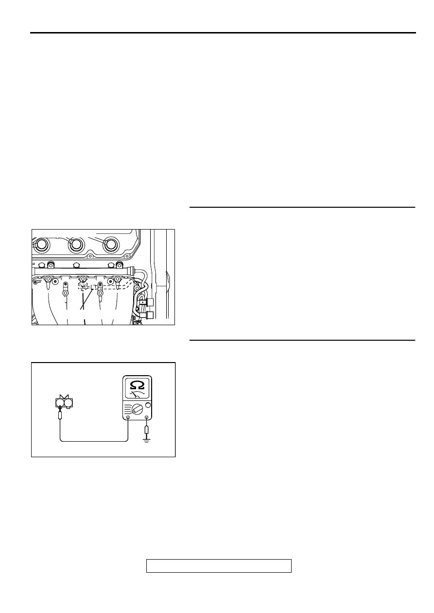
STEP 1 Check connector B-35 at the knock sensor for
damage.
Q: Is the connector in good condition?
YES : Go to Step 2.
NO : Repair or replace it. Refer to GROUP 00E, Harness
Connector Inspection (
). Then go to Step 6.
STEP 2 Check the continuity at knock sensor harness side
connector B-35.
(1) Disconnect the connector B-35 and measure at the harness
side.
(2) Check for the continuity between terminal 2 and ground.
•
Should be less than 2 ohm.
Q: Is the continuity normal?
YES : Go to Step 3.
NO : Repair harness wire between knock sensor connector
B-35 terminal 2 and ground because of open circuit or
harness damage. Then go to Step 6.
AK000100
CONNECTOR:B-35
KNOCK SENSOR
AF
AKX01415
2 1
B-35 HARNESS
SIDE CONNECTOR
AF
MULTIPORT FUEL INJECTION (MFI) DIAGNOSIS
TSB Revision
MULTIPORT FUEL INJECTION (MFI) <3.0L ENGINE>
13B-246
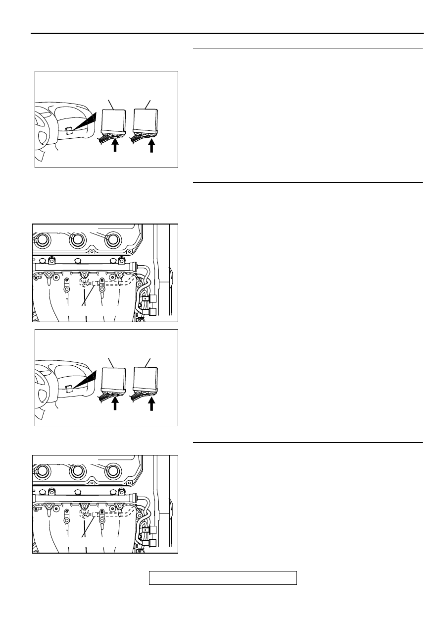
STEP 3. Check connector C-62 at ECM <M/T> or connector
C-59 at PCM <A/T> for damage.
Q: Is the connector in good condition?
YES : Go to Step 4.
NO : Repair or replace it. Refer to GROUP 00E, Harness
Connector Inspection (
). Then go to Step 6.
STEP 4. Check for open circuit, short circuit to ground and
harness damage between knock sensor connector B-35
terminal 1 and ECM connector C-62 terminal 91 <M/T> or
PCM connector C-59 terminal 90 <A/T>.
Q: Is the harness wire in good condition?
YES : Go to Step 5.
NO : Repair it. Then go to Step 6.
STEP 5. Replace the knock sensor.
(1) Replace the knock sensor.
(2) Carry out a test drive.
(3) Check the diagnostic trouble code (DTC).
Q: Is the DTC P0325 is output?
YES : Replace the ECM or PCM. Then go to Step 6.
NO : The inspection is complete.
AK000225
CONNECTOR : C-62<M/T>, C-59<A/T>
C-59
C-62
PCM<A/T>
ECM<M/T>
AL
AK000100
CONNECTOR:B-35
KNOCK SENSOR
AF
AK000225
CONNECTOR : C-62<M/T>, C-59<A/T>
C-59
C-62
PCM<A/T>
ECM<M/T>
AL
AK000100
CONNECTOR:B-35
KNOCK SENSOR
AF
Нет комментариевНе стесняйтесь поделиться с нами вашим ценным мнением.
Текст