Mitsubishi Colt Ralliart. Manual — part 739
TROUBLESHOOTING
MULTIPORT FUEL INJECTION (MPI) <4G1>
13B-281
Inspection Procedure 20: Poor A/C Performance
COMMENT ON TROUBLE SYMPTOM
• Failure is possibly caused by short/overcharged
A/C refrigerant, failed A/C control system, failed
fan control system, or other faults.
PROBABLE CAUSES
• Short- or overcharged A/C refrigerant
• Failed A/C compressor relay
• Failed cooling fan control relay
• Failed A/C-ECU
• Failed engine-ECU
DIAGNOSIS PROCEDURE
STEP 1. M.U.T.-III diagnosis code
Q: Is the diagnosis code output?
YES :
Inspection chart for diagnosis code (Refer
to
NO :
Go to Step 2 .
STEP 2. Check A/C compressor magnet clutch
operation.
• Engine: Idling
• A/C set temperature:
Maximum Cool when temperature in cabin is
25
°C or more
Maximum Hot when temperature in cabin is 25
°C
or less
OK:
Magnet clutch active (when A/C is ON)
Magnet clutch inactive (when A/C is OFF)
Q: Is the check result normal?
YES :
Go to Step 4 .
NO :
Go to Step 3 .
STEP 3. M.U.T.-III data list
• Item 49: A/C relay
a. Engine: Idling
b. A/C set temperature:
Maximum Cool when temperature in cabin is
25
°C or more
Maximum Hot when temperature in cabin is
25
°C or less
OK:
ON (when A/C is ON)
OFF (when A/C is OFF)
Q: Is the check result normal?
YES :
Check A/C system, Refer to GROUP 55B
−
Troubleshooting
− Check Chart for
Diagnosis Code
)
NO :
Check A/C compressor relay system (Refer
to Inspection Procedure 24
).
STEP 4. M.U.T.-III actuator test
• Refer to Actuator Test Reference Table
a. Item 20: Cooling fan motor (HI)
b. Item 21: Cooling fan motor (LO)
Q: Are the check results normal?
YES :
Check charged amount of A/C refrigerant
(Refer to GROUP 55A
− On-vehicle Service
− Check The Refrigerant Level
).
NO :
Check fan control relay system (Refer to
Inspection Procedure 23
Main
Index
Group
TOC
TROUBLESHOOTING
MULTIPORT FUEL INJECTION (MPI) <4G1>
13B-282
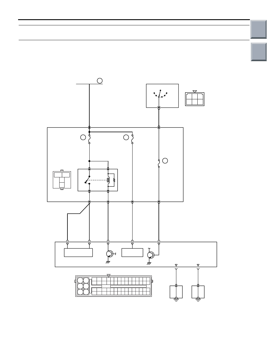
Inspection Procedure 21: Engine-ECU Power Supply, Engine Control Relay, Ignition Switch-IG1
System
AK600600
R
92 93 94 95969798
77 78 79 808182838485868788899091
99
100
107 108 109 110 111112113114115116117118119120121
122 123 124 125126127128129130131132133134135136
101102103104105106
71 72
73 74
75 76
3
1
2
4
1 2 3
4 5 6
B-141
B-106
A-08
R
IG2
ST
LOCK
ACC
IG1
16
1
20A
38
7.5A
Fusible link
Ignition switch
3
2
J/B
122
75
2
76
B
B
3
B-110
B-112
B-112
B-112
B-108
B-129
82
Engine
control
relay
3
1
1
4
2
107
Battery
backup
92
19
23
6
77
Power
source
9
R
R-B
B-O
L-B
G
R
R
Power Supply And Ignition Switch-IG Circuit
43
10A
Wire colour code
B: Black LG: Light green G: Green L: Blue W: White Y: Yellow SB: Sky blue BR: Brown O: Orange GR: Gray
R: Red P: Pink V: Violet P: Purple
Engine-ECU
A-31
J/C
A-30
J/C
AB
GND
GND
Main
Index
Group
TOC

TROUBLESHOOTING
MULTIPORT FUEL INJECTION (MPI) <4G1>
13B-283
OPERATION
• The battery voltage is applied to the engine con-
trol relay (terminal No. 1 and No. 3).
• The engine-ECU (terminal No. 107) makes the
power transistor in the unit be ON position and
makes currents go on the engine control relay
coil, and that makes the relay be in ON position.
• When the engine control relay is in ON position,
the battery voltage is supplied to the
engine-ECU, the sensor and the actuator from
the engine control relay (terminal No. 4).
FUNCTION
• When the ignition switch ON signal is input to the
engine-ECU, the engine-ECU places the engine
control relay in the ON position. Accordingly, the
battery voltage is supplied to the engine-ECU,
sensor and actuator.
PROBABLE CAUSES
• Failed battery
• Failed engine control relay
• Failed ignition switch
• Open/short circuit in or damage to the engine
control relay circuit or loose connector contact
• Open/short circuit in or damage to the ignition
switch-IG1 circuit or loose connector contact
• Open/short circuit in or damage to the
engine-ECU circuit or loose connector contact
• Failed engine-ECU
DIAGNOSIS PROCEDURE
STEP 1. Check battery voltage.
• Measure battery voltage during cranking.
OK: 8 V or more
Q: Is the check result normal?
YES :
Go to Step 2 .
NO :
Check battery (Refer to GROUP 54A
−
Battery
− On-vehicle Service − Battery Test
).
STEP 2. Connector check: B-106 engine control
relay connector
Q: Is the check result normal?
YES :
Go to Step 3 .
NO :
Repair or replace.
STEP 3. Check engine control relay.
• Check engine control relay (Refer to
Q: Is the check result normal?
YES :
Go to Step 4 .
NO :
Replace engine control relay.
3
2
1
4
AK402084
J/B side
connector
B-106
Connector: B-106
J/B (front side)
AC
Main
Index
Group
TOC

TROUBLESHOOTING
MULTIPORT FUEL INJECTION (MPI) <4G1>
13B-284
STEP 4. Perform voltage measurement at B-106
engine control relay connector.
•
Remove relay, and measure at connector side.
• Ignition switch: ON
• Voltage between terminal No. 1 and earth, also
between No. 3 and earth.
OK: System voltage
Q: Is the check result normal?
YES :
Go to Step 5 .
NO :
Check intermediate connector B-108, and
repair if necessary. If intermediate
connector is normal, check and repair
harness between battery and B-106
(terminal No. 1 and No. 3) engine control
relay connector.
• Check power supply line for
open/short circuit.
STEP 5. Connector check: A-08 engine-ECU
connector
Q: Is the check result normal?
YES :
Go to Step 6 .
NO :
Repair or replace.
3
2
1
4
AK402084
J/B side
connector
B-106
Connector: B-106
J/B (front side)
AC
AK402725
77
78
79
80
81
82
83
84
92
93
94
95
96
97
98
99
85
86
87
88
89
90
91
100
101
102
103
104
105
106
115
116
117
118
119
120
121
107
108
109
110
111
112
113
114
130
131
132
133
134
135
136
122
123
124
125
126
127
128
129
72 71
74 73
76 75
R
AI
A-08
Connector:
A-08
A-08 Special tool power plant ECU check
harness
Engine-ECU
Battery
Main
Index
Group
TOC
Нет комментариевНе стесняйтесь поделиться с нами вашим ценным мнением.
Текст