Mitsubishi Colt Ralliart. Manual — part 738

TROUBLESHOOTING
MULTIPORT FUEL INJECTION (MPI) <4G1>
13B-277
Q: Is the check result normal?
YES :
Check intermediate connector B-112, and
repair if necessary. If the intermediate
connector is normal, check and repair
harness between B-127 (terminal No. 2)
cooling fan control relay (HI) connector and
A-08 (terminal No. 96) engine-ECU
connector.
• Check signal line for short circuit.
NO :
Repair or replace.
STEP 7. Connector check: A-20 cooling fan
motor connector
Q: Is the check result normal?
YES :
Go to Step 8 .
NO :
Repair or replace.
STEP 8. Perform resistance measurement at A-20
cooling fan motor connector.
•
Disconnect connector and measure at harness side.
• Resistance between terminal No. 2, No. 4 and
earth.
OK: Continuity (2
Ω or less)
Q: Is the check result normal?
YES :
Go to Step 10 .
NO :
Go to Step 9 .
STEP 9. Connector check: A-31 joint connector
Q: Is the check result normal?
YES :
a. Check and repair harness between
A-20 (terminal No. 2) cooling fan motor
connector and A-31 (terminal No. 2) joint
connector.
b. Check and repair harness between
A-20 (terminal No. 4) cooling fan motor
connector and A-31 (terminal No. 5) joint
connector.
• Check earthing line for damage.
NO :
Repair or replace.
AK402108
2 1
4 3
AC
Connector: A-20
Harness side connector
A-20
AK402108
2 1
4 3
AC
Connector: A-20
Harness side connector
A-20
AK402209
3
2 1
6
5 4
Connector: A-31
Harness side
connector
A-31(G)
AC
AK402108
2 1
4 3
AC
Connector: A-20
Harness side connector
A-20
Main
Index
Group
TOC

TROUBLESHOOTING
MULTIPORT FUEL INJECTION (MPI) <4G1>
13B-278
STEP 10. Connector check: B-114 cooling fan
control relay (LO) connector
Q: Is the check result normal?
YES :
Go to Step 11 .
NO :
Repair or replace.
STEP 11. Check harness between B-114 (terminal
No. 4) cooling fan control relay (LO) connector
and A-20 (terminal No. 1) cooling fan motor
connector.
NOTE: Before checking harness, check intermediate
connector B-109 and repair if necessary.
• Check power supply line for damage.
Q: Is the check result normal?
YES :
Go to Step 12 .
NO :
Repair.
AK402106
3
2
1
4
AC
Connector: B-114
J/B side
connector
B-114
AK402106
3
2
1
4
AC
Connector: B-114
J/B side
connector
B-114
AK402108
2 1
4 3
AC
Connector: A-20
Harness side connector
A-20
Main
Index
Group
TOC
TROUBLESHOOTING
MULTIPORT FUEL INJECTION (MPI) <4G1>
13B-279
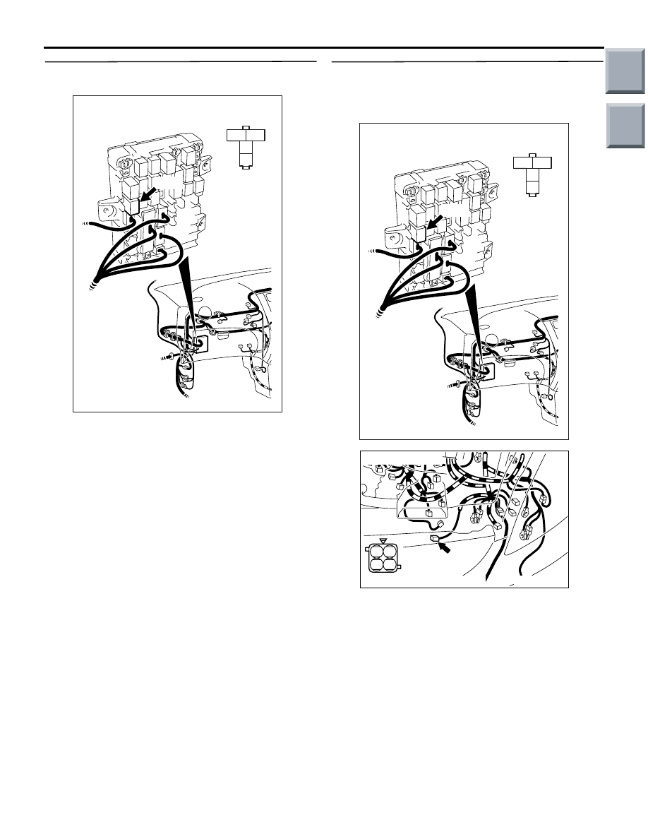
STEP 12. Connector check: B-127 cooling fan
control relay (HI) connector
Q: Is the check result normal?
YES :
Go to Step 13 .
NO :
Repair or replace.
STEP 13. Check harness between B-127 (terminal
No. 4) cooling fan control relay (HI) connector
and A-20 (terminal No. 3) cooling fan motor
connector.
NOTE: Before checking harness, check intermediate
connector B-109 and repair if necessary.
• Check power supply line for damage.
Q: Is the check result normal?
YES :
Go to Step 14 .
NO :
Repair.
3
2
1
4
AK402107
J/B side
connector
Connector: B-127
J/B (front side)
AC
B-127
3
2
1
4
AK402107
J/B side
connector
Connector: B-127
J/B (front side)
AC
B-127
AK402108
2 1
4 3
AC
Connector: A-20
Harness side connector
A-20
Main
Index
Group
TOC

TROUBLESHOOTING
MULTIPORT FUEL INJECTION (MPI) <4G1>
13B-280
STEP 14. Check harness between battery and
B-114 (terminal No. 3) cooling fan control relay
(LO) connector.
NOTE: Before checking harness, check intermediate
connector B-108 and repair if necessary.
• Check power supply line for damage.
Q: Is the check result normal?
YES :
Go to Step 15 .
NO :
Repair.
STEP 15. Check harness between battery and
B-127 (terminal No. 3) cooling fan control relay
(HI) connector.
NOTE: Before checking harness, check intermediate
connector B-108 and repair if necessary.
• Check power supply line for damage.
Q: Is the check result normal?
YES :
Go to Step 16 .
NO :
Repair.
STEP 16. Check the trouble symptom.
Q: Does trouble symptom recur?
YES :
Replace engine-ECU.
NO :
Intermittent malfunction (Refer to GROUP
00
− How to Use
Troubleshooting/Inspection Service Points
−
How to Cope with Intermittent Malfunctions
).
AK402106
3
2
1
4
AC
Connector: B-114
J/B side
connector
B-114
3
2
1
4
AK402107
J/B side
connector
Connector: B-127
J/B (front side)
AC
B-127
Main
Index
Group
TOC
Нет комментариевНе стесняйтесь поделиться с нами вашим ценным мнением.
Текст