Mitsubishi Colt Ralliart. Manual — part 667

AUTOMATIC AIR CONDITIONER PANEL ASSEMBLY (A/C-ECU)
AUTOMATIC AIR CONDITIONER
55B-29
AUTOMATIC AIR CONDITIONER PANEL ASSEMBLY
(A/C-ECU)
REMOVAL AND INSTALLATION
M1552002400541
AC206399 AB
2
1
2
9
3
10
7
5
8
C
C
D
D
A
A
B
B
E
E
C
C
4
6
NOTE
(1) : Clip position
(2) : Claw position
AC208885
Section A – A
Section B – B
Section D – D
AB
Section C – C
Section E – E
Instrument panel
Upper centre
panel
Upper centre
panel
Clip
Instrument
panel
Claw
Claw
Instrument
panel
Console
panel
Console
panel
Clip
Console panel
Instrument
panel
Removal steps
1.
Upper centre panel
2.
Console panel
3.
Ashtray
4.
Lower centre panel
>>
A
5.
Mode selection damper control
cable connection
6.
Heater control panel assembly
Removal steps (Continued)
Main
Index
Group
TOC
AUTOMATIC AIR CONDITIONER PANEL ASSEMBLY (A/C-ECU)
AUTOMATIC AIR CONDITIONER
55B-30
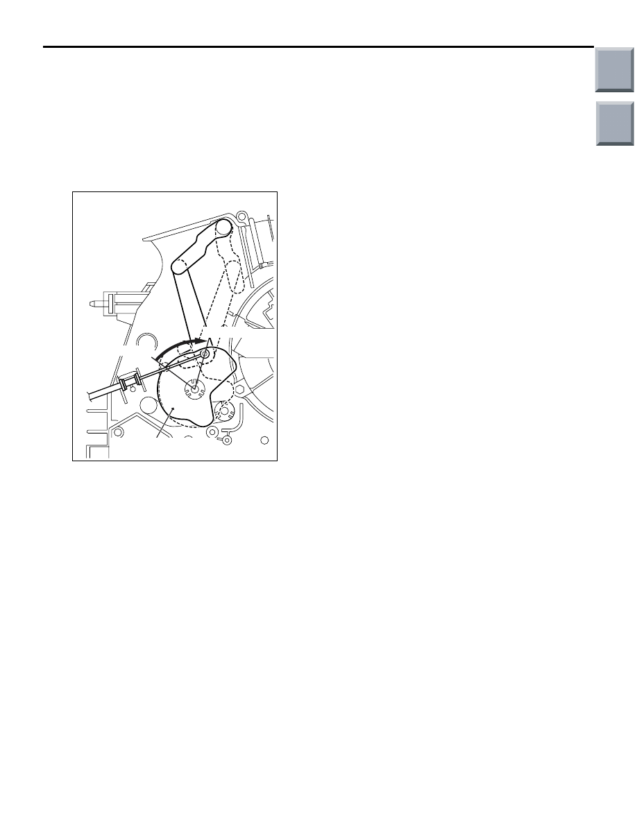
INSTALLATION SERVICE POINT
>>A<< MODE SELECTION DAMPER CON-
TROL CABLE CONNECTION
AC206695
Mode selection damper
control cable connection
AB
FACE position
DEF position
1. Set the air outlet changeover knob of the heater
control assembly to DEF position.
2. Turn the air outlet changeover damper lever of
heater unit to the DEF position (Turn the damper
lever to the left until it stops.) and then install the
cable.
3. Install the cable to the clip and fix it while aligning
the case.
7.
Knob
8.
Heater control assembly
9.
Mode label
10. Heater control panel
Removal steps (Continued)
Main
Index
Group
TOC

AUTOMATIC AIR CONDITIONER PANEL ASSEMBLY (A/C-ECU)
AUTOMATIC AIR CONDITIONER
55B-31
DISASSEMBLY AND REASSEMBLY
M1552014200328
AC206398
6
7
5
4
3
2
1
AB
Disassembly steps
1.
Switch panel
2.
Outside/Inside air selection switch
3.
A/C switch
4.
Rear window defogger switch
5.
Prism
<<
A
>>
6.
Mode selection damper control
cable
7.
Heater control
DISASSEMBLY SERVICE POINT
<<A>> MODE SELECTION DAMPER CON-
TROL CABLE AND AIR MIXING DAMPER
CONTROL CABLE REMOVAL
AC206424
AC
Clip claw
Flat-tipped
screwdriver
To remove the damper cable, insert the flat-tipped
screwdriver from the inside of control base to the clip
and remove the clip claw.
Main
Index
Group
TOC

HEATER UNIT
AUTOMATIC AIR CONDITIONER
55B-32
HEATER UNIT
REMOVAL AND INSTALLATION
M1554009100224
The removal of heater unit is the same as it for the heater, air conditioner and ventilation. (Refer to GROUP
55A, Heater unit and cooling unit
.)
DISASSEMBLY AND REASSEMBLY
M1551005400451
AC208758AB
2
18
23
22
21
13
12
10
9
8
7
3
4
1
24
25
5
18
20
16
17
N
11
6
14
15
19
Disassembly steps
1.
Foot heater duct LH
2.
Foot heater duct RH
3.
Heater joint duct
4.
Heater core
5.
Power transistor
6.
Heater control vacuum aspirator
7.
Blower motor
8.
FACE/DEF plate
9.
Mode main plate
10. FACE/DEF sub plate
11. Air mixing damper control motor
and potentiometer
12. Foot sub plate
13. Foot plate
14. Air mix plate
15. Air mix main plate
16. Expansion valve
17. O ring
18. Heater case
19. Heater lower case
20. Evaporator
21. Mode selection damper control
(FACE)
22. Mode selection damper (FOOT)
23. Air mixing damper
24. Air thermo sensor clip
25. Air thermo sensor
Disassembly steps (Continued)
Main
Index
Group
TOC
Нет комментариевНе стесняйтесь поделиться с нами вашим ценным мнением.
Текст