Mitsubishi Colt Ralliart. Manual — part 668

SENSORS
AUTOMATIC AIR CONDITIONER
55B-33
SENSORS
REMOVAL AND INSTALLATION
M1554001900163
AC207765
2
1
4
5
AB
3
Air mixing damper control motor
and potentiometer removal step
•
Lower panel (Refer to GROUP 52A,
Instrument Panel
1.
Air mixing damper control motor
and potentiometer
Interior temperature sensor
removal steps
•
Lower panel (Refer to GROUP 52A,
Instrument Panel
2.
Interior temperature sensor
3.
Aspirator hose
Power transistor removal step
•
Glove box (Refer to GROUP 52A,
Instrument Panel
•
Front scuff plate and cowl side trim
(Refer to GROUP 52A, Interior Trim
4.
Power transistor
Photo sensor removal step
•
Combination meter (Refer to
GROUP 54A, Combination Meter
<<
A
>>
5.
Photo sensor
Main
Index
Group
TOC
SENSORS
AUTOMATIC AIR CONDITIONER
55B-34
REMOVAL SERVICE POINT
<<A>> PHOTO SENSOR REMOVAL
AC208508AB
Steering wheel
Photo sensor
connector
String
Tie the photo sensor connector with string so that the
connector can be connected easily.
INSPECTION
M1554002000163
CHECK THE INTERIOR TEMPERATURE
SENSOR
AC103488
20
15
10
5
0
-10 0
20
40
60
80
AB
Resis
tance
(k
Ω)
Temperature (˚C)
Check that the resistance shown in the graph is
almost satisfied when measuring the resistance
between the terminals under two or more different
temperature conditions.
NOTE: The temperature condition in checking
should be within the range shown.
CHECK THE AIR MIXING DAMPER CON-
TROL MOTOR AND POTENTIOMETER
AC206696
MAX COOL
position
4
1 2 3
7
5 6
AB
MAX HOT
position
CAUTION
Stop energizing when the lever is set to the oper-
ation stopping position.
MOTOR CHECK
Battery
connection (+)
terminal
Battery
connection (-)
terminal
Lever
operation
1
2
Rotate to the
HOT side.
2
1
Rotate to the
COOL side.
Potentiometer check
When the resistance value between connector termi-
nals 3 and 5 is measured while checking the motor,
check that the resistance value changes gradually
within the standard value.
Standard value: 1.20 (MAX HOT)
− 4.80 (MAX
COOL) k
Ω
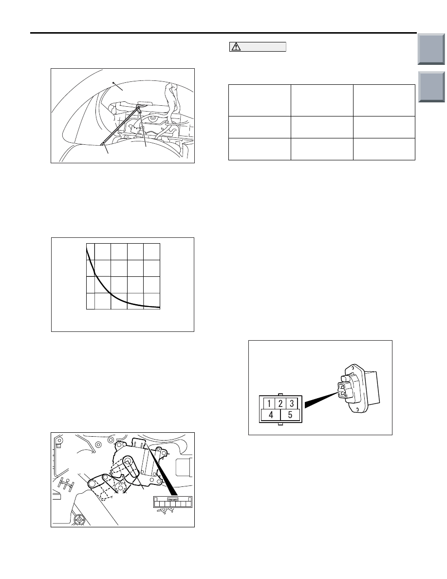
CHECK THE PHOTO SENSER
1. Connect the M.U.T.-III, and check the data list of
the photo sensor.
2. Check that the displayed value changes when
the photo sensor is covered with hands.
CHECK THE POWER TRANSISTOR
Check the thermal fuse.
AC309768
When the resistance between connector terminals 3
and 4 is measured, check that the resistance value is
within the standard value.
Standard value: Approximately 11 k
Ω
TRANSISTOR CHECK
Connect the (-) side clip of the tester to connector
terminal No.4 and the (+) side clip of the tester to ter-
minal No.5, and check that there is not a short or
open circuit in the transistor.
Main
Index
Group
TOC

COMPRESSOR ASSEMBLY
AUTOMATIC AIR CONDITIONER
55B-35
COMPRESSOR ASSEMBLY
REMOVAL AND INSTALLATION <4G1>
M1552004400815
Pre-removal Operation
• Refrigerant Discharging (Refer to
.)
• Front under cover panel assembly (Refer to GROUP 51,
Front Bumper Assembly
Post-installation Operation
• Refrigerant Charging (Refer to
• Drive Belt Tension Adjustment (Refer to GROUP 11C,
On-Vehicle Service, Drive Belt Tension Check And Adjust-
• Front under cover panel assembly installation (Refer to
GROUP 51, Front Bumper Assembly
.)
AC206956
1, 2
3
3
N
4
2
1
6
5
AB
25 ± 4 N·m
7
48 ± 6 N·m
-Pipe coupling
A/C compressor oil:
SUN PAG 56
Removal steps
<<
A
>>
1.
Flexible suction hose connection
<<
A
>>
2.
Flexible discharge hose connection
3.
O-ring
<<
B
>>
4.
Drive belt
<<
C
>>
>>
A
5.
A/C compressor assembly
6.
A/C compressor bracket
7.
A/C drive belt tensioner assembly
Removal steps (Continued)
Main
Index
Group
TOC

OTHER PARTS
AUTOMATIC AIR CONDITIONER
55B-36
REMOVAL SERVICE POINTS
<<A>> FLEXIBLE SUCTION HOSE AND
FLEXIBLE DISCHARGE HOSE DISCON-
NECTION
CAUTION
Use the plug which is not breathable because
A/C compressor oil or receiver have high hygro-
scopicity.
Plug the removed nipple of the pipe, hose and
expansion valve to prevent the entry of dust and dirt.
<<B>> A/C COMPRESSOR DRIVE BELT
REMOVAL
AC205665AB
Adjusting bolt
Tensioner
pulley
Locking nut
1. Loosen the locking nut of the tensioner pulley
CAUTION
To reuse the drive belt, draw an arrow indicating
the rotating direction (clockwise) on the back of
the belt using chalk, etc.
2. Rotate the adjusting bolt to the anti-clockwise
direction (to the left), and remove the drive belt.
<<C>> A/C COMPRESSOR REMOVAL
Be careful not to spill the A/C compressor oil and
remove the A/C compressor.
INSTALLATION SERVICE POINT
>>A<< A/C COMPRESSOR INSTALLA-
TION
When installing the new A/C compressor, install the
A/C compressor after adjusting the oil volume as fol-
lows.
1. Measure the oil of A/C compressor removed.(X
cm
3
)
2. Drain the oil (Y cm
3
) given by the following
expression from a new A/C compressor, and then
install the A/C compressor.
140 cm
3
- X cm
3
= Y cm
3
NOTE:
.
•
140 cm
3
shows the oil volume contained in the
new A/C compressor.
•
Y cm
3
shows the oil volume stored in the
refrigerant line, condenser, and cooling unit,
etc.
OTHER PARTS
OTHER PARTS
M1554004000363
The other service procedures and components are
the same as the heater and the manual air condi-
tioner.
• On-vehicle service
• Air intake box
• Blower motor and outside/inside air selection
damper control motor
• Ambient temperature sensor
• Compressor
• Condenser assembly
• Refrigerant line
• Ducts
• Ventilation
Main
Index
Group
TOC
Нет комментариевНе стесняйтесь поделиться с нами вашим ценным мнением.
Текст