Mitsubishi Colt Ralliart. Manual — part 695
TROUBLESHOOTING
MULTIPORT FUEL INJECTION (MPI) <4G1>
13B-105
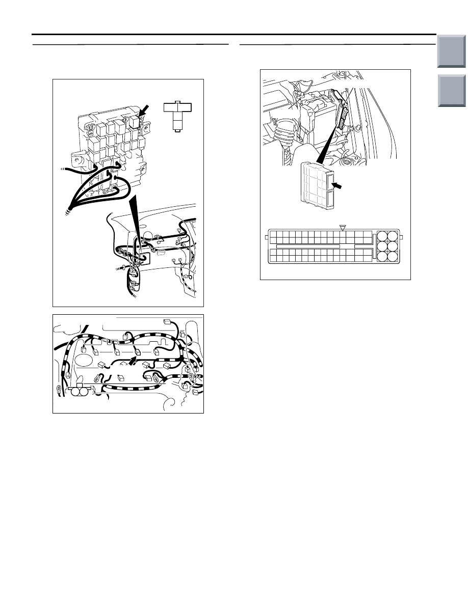
STEP 7. Check harness between B-106 (terminal
No. 4) engine control relay connector and A-104
(terminal No. 1) injector connector.
NOTE: Before checking harness, check intermediate
connectors A-17 and B-112, and repair if necessary.
• Check power supply line for damage.
Q: Is the check result normal?
YES :
Go to Step 8 .
NO :
Repair.
STEP 8. Connector check: A-114 engine-ECU
connector
Q: Is the check result normal?
YES :
Go to Step 9 .
NO :
Repair or replace.
3
2
1
4
AK402084
J/B side
connector
B-106
Connector: B-106
J/B (front side)
AC
AK402090
M
1
2
A-104(G)
AC
Connector: A-104
Harness side
connector
AK402745
6
4
2
5
3
1
9
7
8
10
11
12
13
14
15
16
17
18
19
20
21
22
23
24
25
26
27
28
29
30
31
32
33
34
35
36
37
38
39
40
41
42
43
44
45
46
47
48
49
50
51
52
53
54
55
56
57
58
59
60
61
62
63
64
65
66
L
AF
A-114
Connector:
A-114
Harness side connector
Engine-ECU
Battery
Main
Index
Group
TOC
TROUBLESHOOTING
MULTIPORT FUEL INJECTION (MPI) <4G1>
13B-106
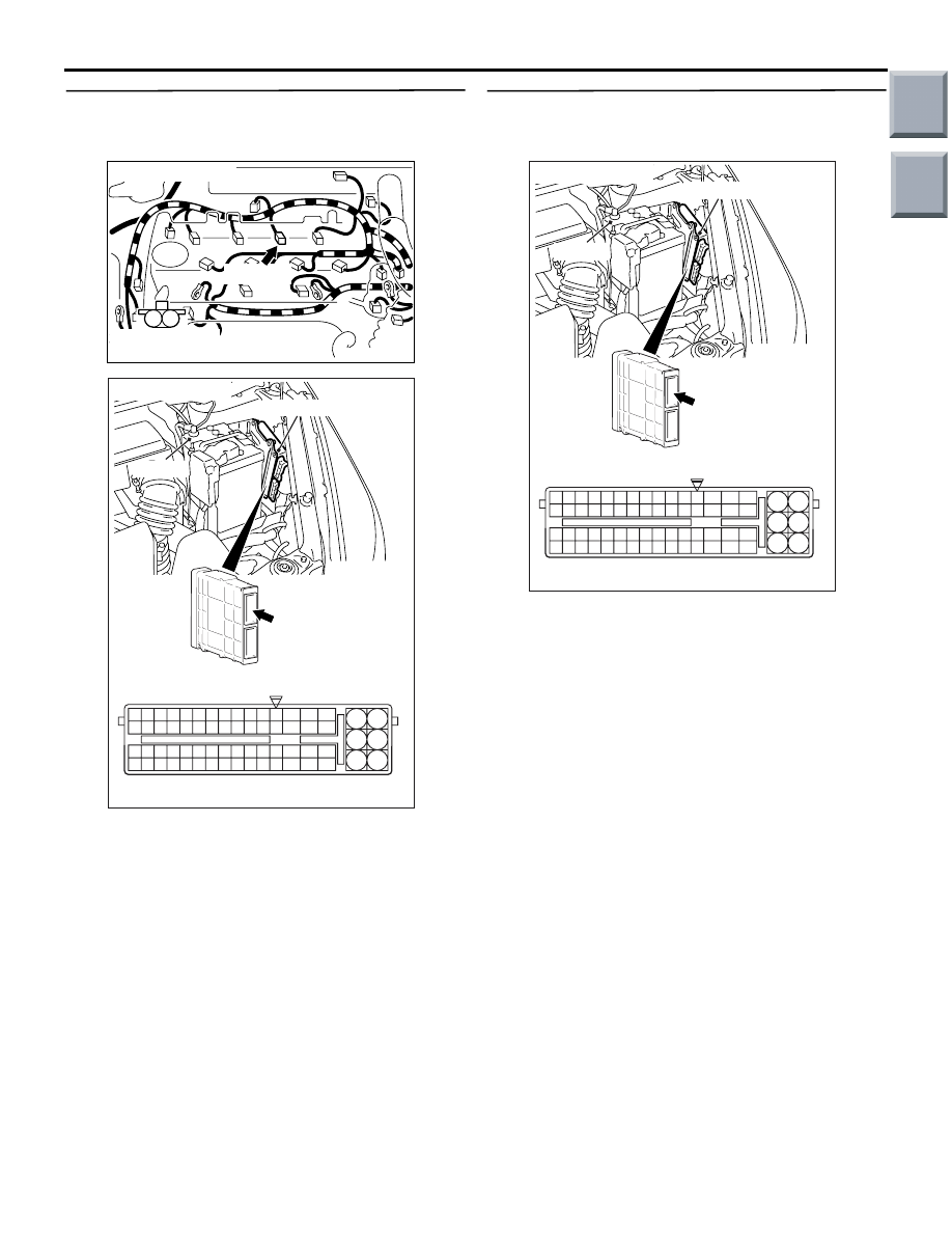
STEP 9. Check harness between A-104 (terminal
No. 2) injector connector and A-114 (terminal No.
23) engine-ECU connector.
• Check output line for open/short circuit and dam-
age.
Q: Is the check result normal?
YES :
Go to Step 10 .
NO :
Repair.
STEP 10. Perform signal wave pattern
measurement at A-114 engine-ECU connector
(using an oscilloscope).
• Disconnect engine-ECU connector, and connect
special tool power plant ECU check harness
(MB991987) and measure the voltage on the
check connector.
• Engine: Idling
• Transmission: Neutral
• Voltage between terminal No. 23 and earth.
OK: Waveform as shown in Inspection Pro-
cedure with Oscilloscope (Refer to
) should be displayed.
Q: Is the check result normal?
YES :
Intermittent malfunction (Refer to GROUP
00
− How to Use
Troubleshooting/Inspection Service Points
−
How to Cope with Intermittent Malfunctions
).
NO :
Replace engine-ECU.
AK402090
M
1
2
A-104(G)
AC
Connector: A-104
Harness side
connector
AK402745
6
4
2
5
3
1
9
7
8
10
11
12
13
14
15
16
17
18
19
20
21
22
23
24
25
26
27
28
29
30
31
32
33
34
35
36
37
38
39
40
41
42
43
44
45
46
47
48
49
50
51
52
53
54
55
56
57
58
59
60
61
62
63
64
65
66
L
AF
A-114
Connector:
A-114
Harness side connector
Engine-ECU
Battery
AK402745
6
4
2
5
3
1
9
7
8
10
11
12
13
14
15
16
17
18
19
20
21
22
23
24
25
26
27
28
29
30
31
32
33
34
35
36
37
38
39
40
41
42
43
44
45
46
47
48
49
50
51
52
53
54
55
56
57
58
59
60
61
62
63
64
65
66
L
AF
A-114
Connector:
A-114
Harness side connector
Engine-ECU
Battery
Main
Index
Group
TOC

TROUBLESHOOTING
MULTIPORT FUEL INJECTION (MPI) <4G1>
13B-107
Code No. P0204: No. 4 Injector System
OPERATION
• Power is supplied to the injector (terminal No. 1)
through the engine control relay (terminal No. 4).
• The engine-ECU (terminal No. 24) turns on the
power transistor in the unit to activate the injector
(terminal No. 2).
AK402684
2
1
3
1
2
4
19
21
20
18
17
16
15
14
1213
11
8 9
L
10
37
52 53 54 555657585960616263646566
38 39 404142434445464748495051
22 23 24 252627282930313233343536
7
5
3
1
6
4
2
A-114
AQ
B-106
A-17
B-112
B-108
Engine
control
relay
Injector
No. 4
A-105
(MU802062)
4
6
4
1
2
2
24
No. 4 Injector Circuit
R
R
Wire colour code
B: Black LG: Light green G: Green L: Blue W: White Y: Yellow SB: Sky blue BR: Brown O: Orange GR: Gray
R: Red P: Pink V: Violet P: Purple
L
3
1
1
1
R
Fusible link
16
20A
J/B
To engine-ECU
Engine-ECU
Main
Index
Group
TOC

TROUBLESHOOTING
MULTIPORT FUEL INJECTION (MPI) <4G1>
13B-108
FUNCTION
• The engine-ECU controls the injector activation
time.
• The fuel injection amount from the injector
depends on the injector activation time.
TROUBLE JUDGEMENT
Check Conditions
• Engine speed is more than 50 r/min and is less
than 1,000 r/min.
• Throttle position sensor (main) output voltage is
less than 1.0 V.
• Not during fuel cut or forced injector-driving (actu-
ator test)
Judgement Criterion
• Injector coil surge voltage (battery voltage plus 2
V) is not detected for 4 seconds.
PROBABLE CAUSES
• Failed No. 4 injector
• Open/short circuit or damage in No. 4 injector cir-
cuit, or loose connector contact
• Failed engine-ECU
DIAGNOSIS PROCEDURE
STEP 1. M.U.T.-III actuator test
• Item 04: No. 4 injector
Idling state varies.
Q: Is the check result normal?
YES :
Intermittent malfunction (Refer to GROUP
00
− How to Use
Troubleshooting/Inspection Service Points
−
How to Cope with Intermittent Malfunctions
).
NO :
Go to Step 2 .
STEP 2. Connector check: A-105 injector
connector
Q: Is the check result normal?
YES :
Go to Step 3 .
NO :
Repair or replace.
STEP 3. Perform resistance measurement at
A-105 injector connector.
• Disconnect connector, and measure at injector
side.
• Resistance between terminals No. 1 and No. 2.
OK: 10.5
− 13.5 Ω (at 20°C)
Q: Is the check result normal?
YES :
Go to Step 4 .
NO :
Replace No. 4 injector.
STEP 4. Perform voltage measurement at A-105
injector connector.
• Disconnect connector and measure at harness
side.
• Ignition switch: ON
• Voltage between terminal No. 1 and earth.
OK: System voltage
Q: Is the check result normal?
YES :
Go to Step 6 .
NO :
Go to Step 5 .
AK402091
M
1
2
A-105(G)
AC
Connector: A-105
Harness side
connector
AK402091
M
1
2
A-105(G)
AC
Connector: A-105
Harness side
connector
AK402091
M
1
2
A-105(G)
AC
Connector: A-105
Harness side
connector
Main
Index
Group
TOC
Нет комментариевНе стесняйтесь поделиться с нами вашим ценным мнением.
Текст