Mitsubishi Colt Ralliart. Manual — part 221

FRONT DISC BRAKE ASSEMBLY
BASIC BRAKE SYSTEM
35A-30
INSTALLATION SERVICE POINTS
>>A<< BRAKE CALIPER ASSEMBLY
INSTALLATION
1. In order to measure the brake drag force after pad
installation, measure the hub sliding torque in the
forward direction (with no pad attached) using a
spring balance.
CAUTION
Keep grease or other fouling off the pad and
brake disc friction surface.
AC102474
MB990520
MB990520
AB
2. Clean the piston, and press the piston into the
cylinder using the special tool, piston expander
(MB990520).
3. Assemble the pad clip and pad to the caliper
support, and tighten the slide pin bolt to the
specified torque.
Tightening torque: 49
± 4 N⋅m
4. Start the engine, and depress the brake pedal
forcibly two or three times. Then stop the engine.
5. Rotate the brake disc 10 turns in the forward
direction.
AC210114AB
6. Using a spring balance, measure the hub sliding
torque in the forward direction.
7. Obtain the disc brake drag force (difference
between measured values of item 1 and item 6).
Standard value: 83 N or less.
8. If the brake drag force exceeds the standard
value, disassemble the piston to check for
fouling/rust on the piston sliding section and
piston/seal deterioration, and confirm whether the
slide pin slides properly.
>>B<< BRAKE HOSE INSTALLATION
AC403716
A
AC
Brake hose
Wrong
Correct
Bracket
View A
Twist the brake hose towards the lesser torsion
between the brake hose and body bracket as shown,
and secure it to the body bracket.
Main
Index
Group
TOC

FRONT DISC BRAKE ASSEMBLY
BASIC BRAKE SYSTEM
35A-31
REMOVAL AND INSTALLATION <15-INCH (RALLIART Version-R)>
M1351006000957
Pre-removal Operation
Brake fluid draining
Post-installation Operation
Brake fluid refilling and air bleeding (Refer to
).
AC312917AG
N
105 ± 5 N·m
2
1
3
30 ± 4 N·m
4
1
9 ± 1 N·m
15 ± 2 N·m
Removal steps
1.
Connection between brake hose
and brake caliper
2.
Gasket
>>
A
3.
Brake caliper assembly
4.
Brake disc
Removal steps (Continued)
Main
Index
Group
TOC

FRONT DISC BRAKE ASSEMBLY
BASIC BRAKE SYSTEM
35A-32
INSTALLATION SERVICE POINTS
>>A<< BRAKE CALIPER ASSEMBLY
INSTALLATION
1. In order to measure the brake drag force after pad
installation, measure the hub sliding torque in the
forward direction (with no pad attached) using a
spring balance.
CAUTION
Keep grease or other fouling off the pad and
brake disc friction surface.
AC102474
MB990520
MB990520
AB
2. Clean the piston, and press the piston into the
cylinder using the special tool, piston expander
(MB990520).
3. Assemble the pad clip and pad to the caliper
support, and tighten the slide pin bolt to the
specified torque.
Tightening torque: 28
± 2 N⋅m
4. Start the engine, and depress the brake pedal
forcibly two or three times. Then stop the engine.
5. Rotate the brake disc 10 turns in the forward
direction.
AC210114AB
6. Using a spring balance, measure the hub sliding
torque in the forward direction.
7. Obtain the disc brake drag force (difference
between measured values of item 1 and item 6).
Standard value: 95 N or less
8. If the brake drag force exceeds the standard
value, disassemble the piston to check for
fouling/rust on the piston sliding section and
piston/seal deterioration, and confirm whether the
slide pin slides properly.
Main
Index
Group
TOC
FRONT DISC BRAKE ASSEMBLY
BASIC BRAKE SYSTEM
35A-33
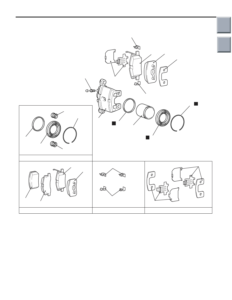
DISASSEMBLY AND REASSEMBLY <14-INCH>
M1351006201017
AC602358
6
1
7.9 ± 0.9 N·m
9
8
N
N
7
2
3
4
5
5
6
8
2
3
2
3
4
4
1
1
AB
N
1
4
Pin boot
Pin boot
Brake caliper kit
Pad set
Shim set
Clip set
Disassembly steps
1. Shim
2. Outer pad
3. Pad assembly <RH>, pad and wear
indicator assembly <LH>
4. Pad clip
5. Boot ring
<<
A
>>
6. Piston boot
<<
A
>>
7. Piston
<<
B
>>
8. Piston seal
9. Caliper body
Disassembly steps (Continued)
Main
Index
Group
TOC
Нет комментариевНе стесняйтесь поделиться с нами вашим ценным мнением.
Текст