Mitsubishi Colt Ralliart. Manual — part 443

TROUBLESHOOTING
POWER STEERING
37-39
Code No.C1532 Over real current of motor
CAUTION
• If the electric power steering-ECU sets diagnosis code No.C1532, diagnose the CAN bus lines. If
there is any fault in the CAN bus lines, an incorrect diagnosis code may be set.
•
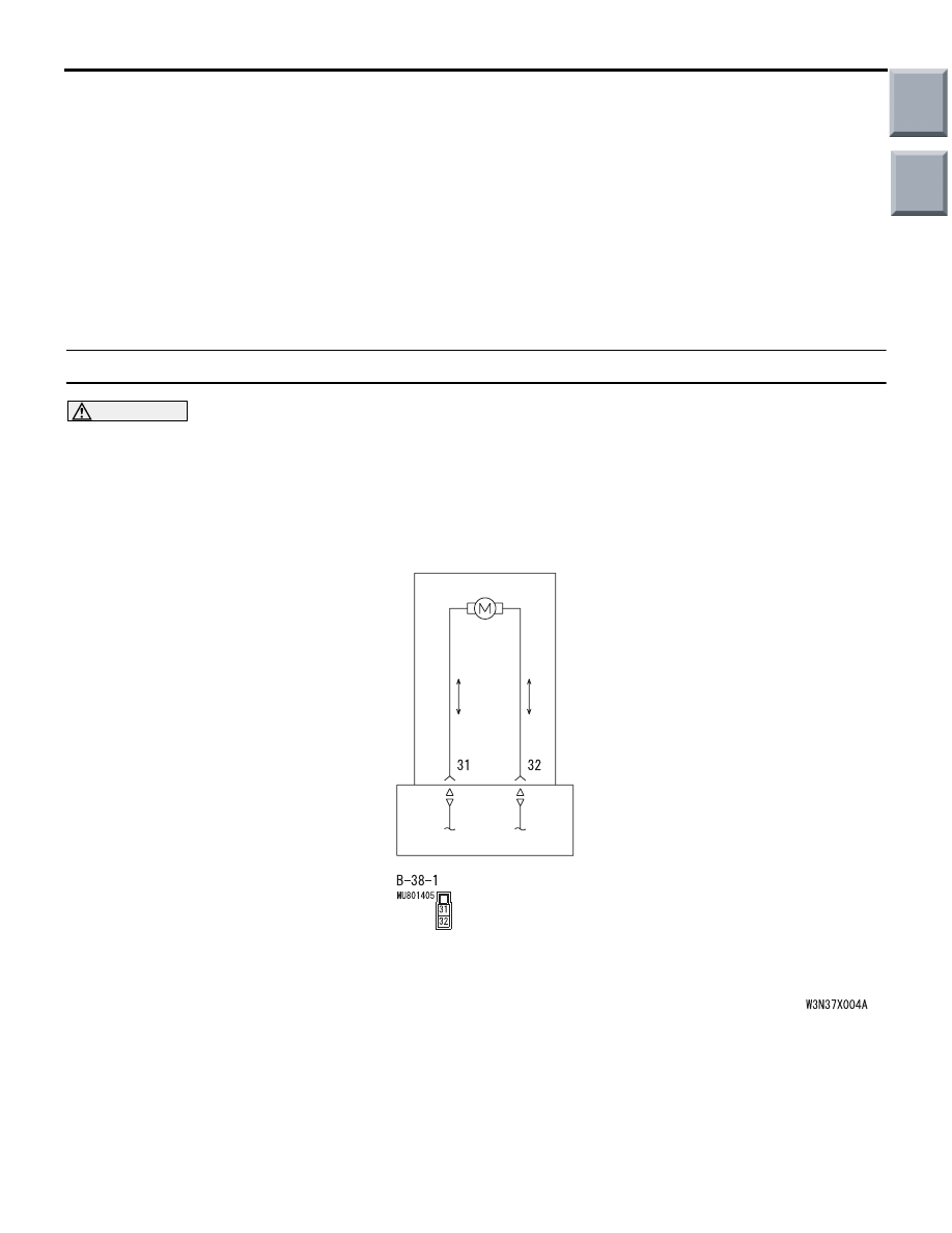
ELECTRIC POWER STEERING-ECU
Wire colour code
B : Black LG : Light green G : Green L : Blue W : White Y : Yellow SB : Sky blue
BR : Brown O : Orange GR : Gray R : Red P : Pink V : Violet
Motor Circuit
Whenever the ECU is replaced, ensure that the communication circuit is normal.
DIAGNOSIS CODE SET CONDITIONS
• The motor current does not meet a predeter-
mined limit stored in the microcomputer, and the
microcomputer determines that there is a prob-
lem in the motor current limit.
Criteria for judging malfunction
• Actual measurement value of the motor cur-
rent (absolute value) is more than 65 A
PROBABLE CAUSES
• Defective harness wire(s) or connector(s)
• Defective motor of the steering gear and linkage
assembly
• Malfunction of the electric power steering-ECU
Main
Index
Group
TOC

TROUBLESHOOTING
POWER STEERING
37-40
DIAGNOSTIC PROCEDURE
STEP 1. M.U.T.-III diagnosis code
AC206895
AC
Diagnosis
connector
MB991827
MB991824
MB991910
CAUTION
Before connecting or disconnecting the
M.U.T.-III, turn the ignition switch to the "LOCK"
(OFF) position.
Check again if the diagnosis code is set.
(1) Turn the ignition switch to the "ON" position.
(2) Erase the diagnosis code.
(3) Turn the ignition switch to the "LOCK" (OFF)
position.
(4) Turn the ignition switch to the "ON" position.
(5) Start the engine, and check the diagnosis code.
(6) Turn the ignition switch to the "LOCK" (OFF)
position.
Q: Is diagnosis code C1531 set?
YES :
Carry out the troubleshooting for diagnosis
code C1531 (Refer to
).
NO :
Go to Step 2.
STEP 2. Check the electric power steering-ECU
connector B-38-1.
•
AC314189AC
Connector: B-38-1
Harness side
B-38-1 electric power steering-ECU connector
Check the connectors above for improper engage-
ment, terminal damage or terminal drawn in the con-
nector case.
Q: Is the check result normal?
YES :
Go to Step 3.
NO :
Repair the connector(s) or terminal(s).
STEP 3. Check whether the diagnosis code is
reset.
AC206895
AC
Diagnosis
connector
MB991827
MB991824
MB991910
CAUTION
Before connecting or disconnecting the
M.U.T.-III, turn the ignition switch to the "LOCK"
(OFF) position.
Check again if the diagnosis code is set.
(1) Turn the ignition switch to the "ON" position.
(2) Erase the diagnosis code.
Main
Index
Group
TOC
TROUBLESHOOTING
POWER STEERING
37-41
(3) Turn the ignition switch to the "LOCK" (OFF)
position.
(4) Turn the ignition switch to the "ON" position.
(5) Start the engine.
(6) Check if the diagnosis code is set.
(7) Turn the ignition switch to the "LOCK" (OFF)
position.
(8) Disconnect M.U.T.-III.
Q: Is diagnosis code C1532 set?
YES :
Replace the electric power steering-ECU
). If the concern is not
eliminated after the electric power
steering-ECU is replaced, replace the power
steering gear box.
NO :
The malfunction is intermittent. Refer to
GROUP 00, How to Use
Troubleshooting/Inspection Service Points
−
How to Cope with Intermittent Malfunction
.
Code No.C1534 Under real current of motor
CAUTION
• If the electric power steering-ECU sets diagnosis code No.C1534, diagnose the CAN bus lines. If
there is any fault in the CAN bus lines, an incorrect diagnosis code may be set.
•
ELECTRIC POWER STEERING-ECU
Wire colour code
B : Black LG : Light green G : Green L : Blue W : White Y : Yellow SB : Sky blue
BR : Brown O : Orange GR : Gray R : Red P : Pink V : Violet
Motor Circuit
Whenever the ECU is replaced, ensure that the communication circuit is normal.
DIAGNOSIS CODE SET CONDITIONS
• The motor current is less than the lower limit of
the assist permission current stored in the micro-
computer, but assist torque is produced. Then the
microcomputer determines that there is a prob-
lem in the motor current.
Criteria for judging malfunction
• Actual measurement value of the motor cur-
rent (absolute value) is 1 A or less and assist
torque (absolute value) is more than 0.3 N
⋅m
Main
Index
Group
TOC
TROUBLESHOOTING
POWER STEERING
37-42
PROBABLE CAUSES
• Defective harness wire(s) or connector(s)
• Malfunction of the electric power steering-ECU
• Motor malfunction
DIAGNOSTIC PROCEDURE
STEP 1. Check the electric power steering-ECU
connector B-38-1.
AC314189AC
Connector: B-38-1
Harness side
• B-38-1 electric power steering-ECU connector
Check the connectors above for improper engage-
ment, terminal damage or terminal drawn in the con-
nector case.
Q: Is the check result normal?
YES :
Go to Step 2.
NO :
Repair the connector(s) or terminal(s).
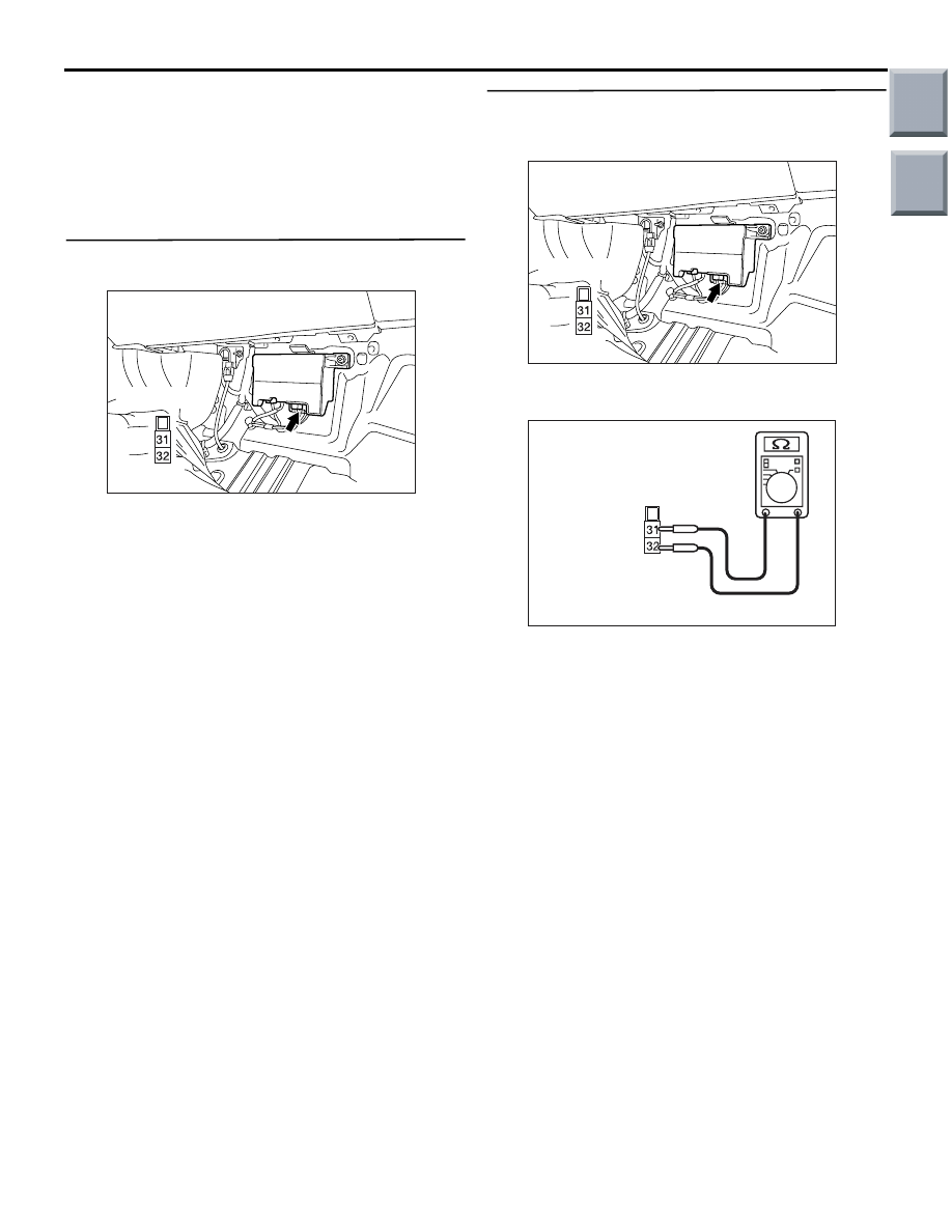
STEP 2. Check the motor wires of the steering
gear and linkage assembly wiring harness for
open circuit.
AC314189AC
Connector: B-38-1
Harness side
Disconnect electric power steering-ECU connector
B-38-1 and measure the resistance.
•
AC400133AB
Harness side
connector B-38-1
(Rear view)
Measure the resistance between electric power
steering-ECU connector B-38-1 terminals 31 and
32.
OK: Continuity exists (2
Ω or less)
Q: Is the check result normal?
YES :
Go to Step 3.
NO :
Repair the harness wire and connector, or
replace the steering gear and linkage
assembly (Refer to
).
Main
Index
Group
TOC
Нет комментариевНе стесняйтесь поделиться с нами вашим ценным мнением.
Текст