Mitsubishi Colt Ralliart. Manual — part 442

TROUBLESHOOTING
POWER STEERING
37-35
STEP 3. M.U.T.-III data list
AC206895
AC
Diagnosis
connector
MB991827
MB991824
MB991910
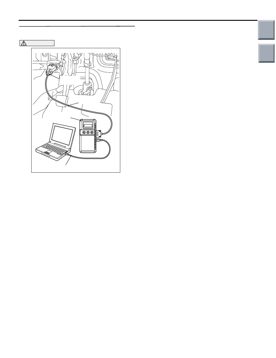
CAUTION
Before connecting or disconnecting the
M.U.T.-III, turn the ignition switch to the "LOCK"
(OFF) position.
Check again if the diagnosis code is set.
(1) Turn the ignition switch to the "ON" position.
(2) Erase the diagnosis code.
(3) Turn the ignition switch to the "LOCK" (OFF)
position.
(4) Turn the ignition switch to the "ON" position.
(5) Start the engine.
(6) Set M.U.T.-III to data reading mode, and check
the data list item.
• Item 12: Engine speed
• Item 87: Tachometer (Refer to GROUP 54A,
Combination meter
− Data list reference table
OK: The tachometer normal and the read-
ing on the tachometer nearly match the
indication on M.U.T.-III.
(7) Turn the ignition switch to the "LOCK" (OFF)
position.
Q: Is the engine speed input normal?
YES :
Go to Step 4.
NO :
Replace the engine-CVT-ECU (Refer to
GROUP 13A, Engine-CVT-ECU
).
STEP 4. Check whether the diagnosis code is
reset.
AC206895
AC
Diagnosis
connector
MB991827
MB991824
MB991910
CAUTION
Before connecting or disconnecting the
M.U.T.-III, turn the ignition switch to the "LOCK"
(OFF) position.
Check again if the diagnosis code is set.
(1) Turn the ignition switch to the "ON" position.
(2) Erase the diagnosis code.
(3) Turn the ignition switch to the "LOCK" (OFF)
position.
(4) Turn the ignition switch to the "ON" position.
(5) Start the engine.
(6) Recheck whether diagnosis code C1522 is set.
(7) Turn the ignition switch to the "LOCK" (OFF)
position.
(8) Disconnect M.U.T.-III.
Q: Is diagnosis code C1522 set?
YES :
Replace the electric power steering-ECU
).
NO :
The malfunction is intermittent. Refer to
GROUP 00, How to Use
Troubleshooting/Inspection Service Points
−
How to Cope with Intermittent Malfunction
.
Main
Index
Group
TOC

TROUBLESHOOTING
POWER STEERING
37-36
Code No.C1531 Motor terminal voltage abnormality
CAUTION
• If the electric power steering-ECU sets diagnosis code No.C1531, diagnose the CAN bus lines. If
there is any fault in the CAN bus lines, an incorrect diagnosis code may be set.
•
ELECTRIC POWER STEERING-ECU
Wire colour code
B : Black LG : Light green G : Green L : Blue W : White Y : Yellow SB : Sky blue
BR : Brown O : Orange GR : Gray R : Red P : Pink V : Violet
Motor Circuit
Whenever the ECU is replaced, ensure that the communication circuit is normal.
DIAGNOSIS CODE SET CONDITIONS
• The motor terminal voltage does not meet a pre-
determined voltage stored in the microcomputer,
and the microcomputer determines that there is a
problem in the motor terminal voltage.
Criteria for judging malfunction
• Right and left terminal voltages of the motor
are less than 0.5 V.
• Both right and left terminal voltages of the
motor are more than the power supply voltage
− 1.13 V.
PROBABLE CAUSES
• Defective harness wire(s) or connector(s)
• Defective motor of the steering gear and linkage
assembly
• Malfunction of the electric power steering-ECU
Main
Index
Group
TOC
TROUBLESHOOTING
POWER STEERING
37-37
DIAGNOSTIC PROCEDURE
STEP 1. Check the electric power steering-ECU
connector B-38-1.
•
AC314189AC
Connector: B-38-1
Harness side
B-38-1 electric power steering-ECU connector
Check the connectors above for improper engage-
ment, terminal damage or terminal drawn in the con-
nector case.
Q: Is the check result normal?
YES :
Go to Step 2.
NO :
Repair the connector(s) or terminal(s).
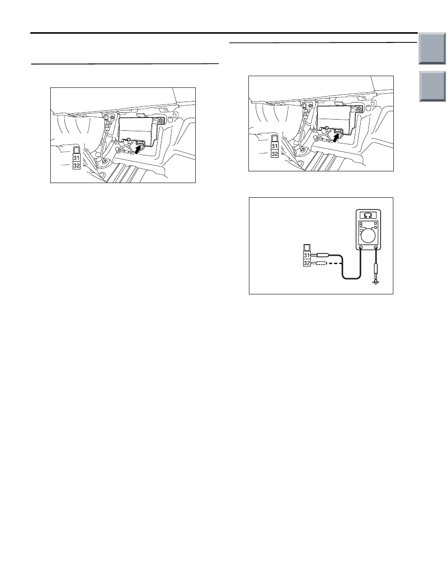
STEP 2. Check the motor wires of the steering
gear and linkage assembly wiring harness for
short to earth.
AC314189AC
Connector: B-38-1
Harness side
Disconnect electric power steering-ECU connector
B-38-1 and measure the resistance.
•
AC313972BV
Harness side
connector B-38-1
(Rear view)
Measure the resistance between electric power
steering-ECU connector B-38-1 terminal 31 and
body earth.
• Measure the resistance between electric power
steering-ECU connector B-38-1 terminal 32 and
body earth.
OK: Open circuit or more than 300
Ω
Q: Is the check result normal?
YES :
Go to Step 3.
NO :
Replace the steering gear and linkage
assembly (Refer to
).
Main
Index
Group
TOC
TROUBLESHOOTING
POWER STEERING
37-38
STEP 3. Check whether the diagnosis code is
reset.
AC206895
AC
Diagnosis
connector
MB991827
MB991824
MB991910
CAUTION
Before connecting or disconnecting the
M.U.T.-III, turn the ignition switch to the "LOCK"
(OFF) position.
Check again if the diagnosis code is set.
(1) Turn the ignition switch to the "ON" position.
(2) Erase the diagnosis code.
(3) Turn the ignition switch to the "LOCK" (OFF)
position.
(4) Turn the ignition switch to the "ON" position.
(5) Start the engine.
(6) Recheck whether diagnosis code C1531 is set.
(7) Turn the ignition switch to the "LOCK" (OFF)
position.
(8) Disconnect M.U.T.-III.
Q: Is diagnosis code C1531 set?
YES :
Replace the electric power steering-ECU
).
NO :
The malfunction is intermittent. Refer to
GROUP 00, How to Use
Troubleshooting/Inspection Service Points
−
How to Cope with Intermittent Malfunction
.
Main
Index
Group
TOC
Нет комментариевНе стесняйтесь поделиться с нами вашим ценным мнением.
Текст