Mitsubishi Colt Ralliart. Manual — part 200

ON-VEHICLE SERVICE
CVT
23A-143
SELECTOR LEVER OPERATION CHECK
M1231202900113
1. Depress and hold the parking brake pedal.
AC509407
AB
P
R
N
D
Ds
L
: Turn the ignition switch to the position other
than LOCK, depress the brake pedal.
Then operate while pushing the button.
: Operate without pushing the button.
: Operate while pushing the button.
2. Check that the selector lever can be moved
through each range smoothly and securely.
3. Check that the engine starts when the selector
lever is in the N or P position, and that it does not
start when the selector lever is in any other
position.
4. Start the engine, and then depress the parking
brake pedal again to release it.
5. The vehicle should move forward when the
selector lever is moved into D or Ds range, and
moves backward when moved into R range.
6. Stop the engine.
7. Turn the ignition switch to the ON position, and
check that the backup lamp illuminates when the
selector lever is shifted from the P position to the
R position.
NOTE: The A/T mis-operation prevention mecha-
nism prevents movement of the selector lever
from the P position if the ignition switch is in a
position other than LOCK (OFF) position and the
brake pedal is not depressed.
Main
Index
Group
TOC

ON-VEHICLE SERVICE
CVT
23A-144
KEY INTERLOCK/SHIFT LOCK
MECHANISM CHECK AND ADJUSTMENT
M1232003100614
1. Carry out the following check.
<Key interlock side>
Inspection
procedure
Inspection conditions
Check details (normal condition)
1
Brake pedal:
Depressed
Ignition key position:
LOCK (OFF) or pulled out
The selector lever push button cannot be
pushed, and the selector lever should not be
moved from P position.
2
Ignition key position: Other
than above
The selector lever push button can be pushed,
and the selector lever can be moved from P
position.
3
Selector lever position: Other than P position The ignition key cannot turned to LOCK (OFF)
position.
4
Selector lever position: P position
The ignition key can be turned to LOCK (OFF)
position.
<Shift lock side>
Inspection
procedure
Inspection conditions
Check details (normal condition)
1
Ignition switch
position: ACC
Brake pedal: Depressed
The selector lever push button can be pushed,
and the selector lever can be moved from P
position.
2
Brake pedal: Not
depressed
The selector lever push button cannot be
pushed, and the selector lever should not be
moved from P position.
2. If the operations above are abnormal, check the
shift lock cable unit in the following procedures.
(1) Remove the instrument lower panel (Refer to
GROUP 52A
− Instrument Panel Assembly
).
(2) Remove the steering column lower cover
(Refer to GROUP 37
− Steering Shaft
).
(3) Shift the selector lever to the P position.
(4) Turn the ignition switch to the LOCK (OFF)
position.
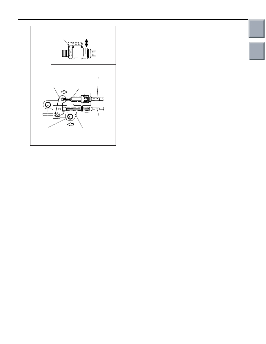
(5) Lift the lock guide of the key interlocking cable
and then unlock it.
Main
Index
Group
TOC
AC000004
B
C
A
View A
Lock guide
AC
Lock released
Locked
Key interlock cable
Cap
Lever
Shift lock cable
Shift lock
cable unit
Fixing bolt
ON-VEHICLE SERVICE
CVT
23A-145
(6) Loosen the bolts fixing the shift lock cable unit,
push the lever in direction B and tighten the
bolts to the specified torque.
Tightening torque: 5.0
± 1.0 N⋅m
(7) Lower the lock guide of the key interlocking
cable and then lock it.
NOTE: The key interlocking cable is adjusted
according to the lock position (cap push state)
at this time. Readjust the lock position if key
interlocking operations malfunction after lock-
ing.
3. After adjustment, re-check the operations.
Replace the shift lock cable unit if operations are
defective (Refer to
).
Main
Index
Group
TOC

TRANSMISSION CONTROL
CVT
23A-146
TRANSMISSION CONTROL
REMOVAL AND INSTALLATION
M1231203200173
CAUTION
When removing and installing the transmission control cable and shift lock cable unit, be careful not
to hit the SRS-ECU.
Pre-removal Operation
• Steering column lower cover and instrument lower panel
removal (Refer to GROUP 52A, Instrument Panel Assem-
bly
).
Post-installation Operation
• Key interlock and shift lock mechanism check (Refer to
).
• Selector lever operation check (Refer to
).
• Steering column lower cover and instrument lower panel
installation (Refer to GROUP 52A, Instrument Panel
Assembly
).
AC309755
AC208301
AB
1
2
4
12 ± 2 N·m
5.0 ± 1.0 N·m
12 ± 2 N·m
5.0 ± 1.0 N·m
7
8
9
3
5
6
Removal steps
•
Shift the selector lever to the N position.
•
Air cleaner assembly
•
Battery and battery tray
•
Connectors and clamps around
steering column assembly
1. Shift lock cable connection
<<
A
>> >>
D
<< 2. Key interlock rod connection
>>
C
<< 3. Shift lock rod connection
>>
C
<< 4. Shift lock cable unit
>>
B
<< 5. Transmission control cable connection
(selector lever side)
6. Selector lever assembly
>>
A
<< 7. Transmission control cable connection
(transmission side)
8. Adjuster
9. Transmission control cable
Removal steps (Continued)
Main
Index
Group
TOC
Нет комментариевНе стесняйтесь поделиться с нами вашим ценным мнением.
Текст