Mitsubishi Colt Ralliart. Manual — part 385
SYMPTOM PROCEDURES
SMART WIRING SYSTEM (SWS) USING SWS MONITOR
54C-48
Step 4. ECU check by using the SWS monitor
Check that the power supply and earth lines to the
ETACS-ECU and the SWS communication lines are
normal.
• Ignition switch: ON
ECU TO BE CHECKED
• ETACS ECU
OK: "OK" is displayed on the "ETACS ECU"
menu.
Q: Is the check result normal?
YES :
Go to Step 5.
NO :
Refer to Inspection Procedure A-3
"Communication with the ETACS-ECU is
not possible
Step 5. SWS monitor data list
Check the SWS communication signal, which is
related to the door-ajar warning buzzer function.
<Selected item> ETACS ECU
• Ignition switch: ON
• Driver’s door: Open
OK: Normal condition is displayed.
Q: Is the check result normal?
Normal conditions are displayed for all the items. :
Go to Step 6.
Normal condition is not displayed for item No.30. :
Refer to inspection procedure N-2 "The
ignition switch (IG1) signal is not received
."
Normal condition is not displayed for item No.32. :
Refer to inspection procedure N-3 "The
driver's door switch signal is not received
."
Normal condition is not displayed for item No.43. :
Replace the ETACS-ECU.
Step 6. ETACS switch data by using the SWS
monitor
Check the ETACS-ECU input signal related to the
door-ajar warning buzzer function.
• Doors other than the driver's door (including the
tailgate): Closed to open
OK: Normal condition is displayed.
Q: Is the check result normal?
YES :
Go to Step 7.
NO :
Refer to inspection procedure N-10 "All the
door switch signals are not received
."
Step 7. Retest the system.
Check that the door-ajar warning buzzer function
works normally.
Q: Is the check result normal?
YES :
The trouble can be an intermittent
malfunction (Refer to GROUP 00
− How to
use Troubleshooting/inspection Service
Points
− How to Cope with Intermittent
).
NO :
Replace the ETACS-ECU.
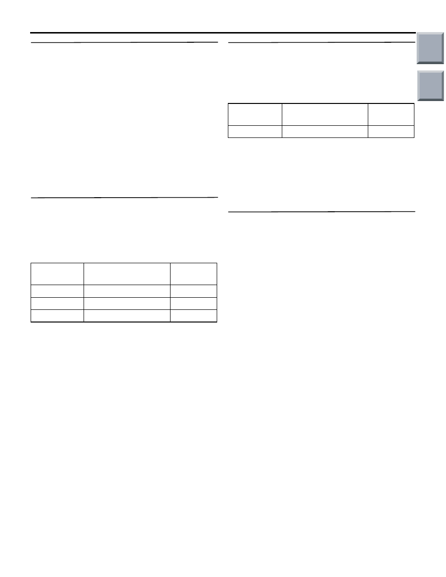
Item No.
Item name
Normal
condition
Item 30
IG SW(IG1)
ON
Item 32
DR DOOR SW
ON
Item 43
BUZZER
ON
Item No.
Item name
Normal
condition
Item 40
ALL DOOR SW
ON
Main
Index
Group
TOC
SYMPTOM PROCEDURES
SMART WIRING SYSTEM (SWS) USING SWS MONITOR
54C-49
INSPECTION PROCEDURE B-3: Turn-signal lamp operation sound function does not work normally.
CAUTION
Whenever the ECU is replaced, ensure that the
input and output signal circuits are normal.
COMMENTS ON TROUBLE SYMPTOM
The ETACS-ECU operates this function in accord-
ance with the input signals below.
• Turn-signal lamp switch
• Hazard warning lamp switch
If this function does not work normally, these input
signal circuit(s) or the ETACS-ECU may be defec-
tive. Note that this function can be disabled/enabled
by the customisation function (default setting; disa-
bled). In order to change the setting, the SWS moni-
tor is required.
POSSIBLE CAUSES
• Malfunction of the column switch
• Malfunction of the ETACS-ECU
• Damaged harness wires and connectors
DIAGNOSTIC PROCEDURE
Step 1. Check that the turn-signal lamps operate.
When the turn-signal lamp switch or the hazard
warning lamp switch is operated, check that the
turn-signal lamps flash.
Q: Is the check result normal?
YES :
Go to Step 2.
NO :
First, repair the turn-signal lamp(s) (Refer to
Trouble Symptom Chart
).
Step 2. Customize function by using the SWS
monitor
Use the SWS monitor customisation function to con-
firm that "T/SIG.BUZZER" is set to "W.FUNCTION".
Q: Is the check result normal?
YES :
Go to Step 3.
NO :
Use the SWS monitor customisation
function to set "T/SIG.BUZZER" to
"W.FUNCTION" (Refer to
Turn-Signal Lamp Operation Sound Function
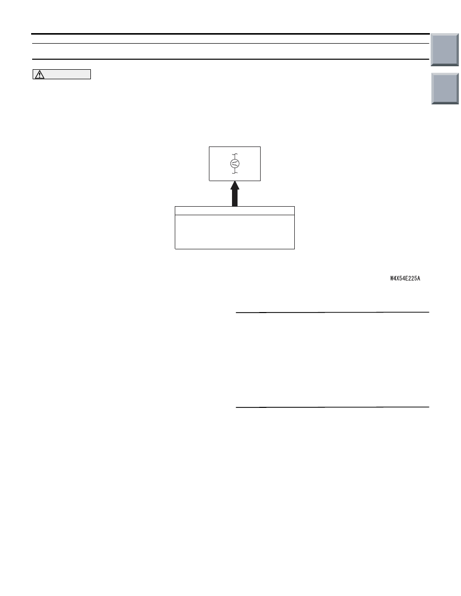
ETACS-ECU
INPUT SIGNAL
·HAZARD WARNING LAMP SWITCH
·IGNITION SWITCH (IG1)
·TURN-SIGNAL SWITCH
Main
Index
Group
TOC

SYMPTOM PROCEDURES
SMART WIRING SYSTEM (SWS) USING SWS MONITOR
54C-50
Step 3. ECU check by using the SWS monitor
Check that the power supply and earth lines to the
ETACS-ECU and the column switch (column-ECU)
and the SWS communication lines are normal.
• Ignition switch: ON
ECU TO BE CHECKED
• ETACS-ECU
• Column ECU
OK: "OK" are displayed for all the items
Q: Is the check result normal?
Normal conditions are displayed for all the items. :
Go to Step 4.
"NG" is displayed on the "ETACS ECU" menu. :
Refer to Inspection Procedure A-3
"Communication with the ETACS-ECU is
not possible
"NG" is displayed on the "COLUMN ECU" menu. :
Refer to Inspection Procedure A-2
"Communication with the column switch
(column-ECU) is not possible
."
Step 4. SWS monitor data list
Check the SWS communication input signal, which
are related to the turn-signal lamp operation sound
function.
<Selected item> ETACS-ECU
• Hazard warning switch: ON
OK: Normal conditions are displayed for all
the items.
Q: Is the check result normal?
YES :
Go to Step 5.
NO :
Replace the ETACS-ECU.
Step 5. Retest the system.
Check that the turn-signal lamp operation sound
function works normally.
Q: Is the check result normal?
YES :
The trouble can be an intermittent
malfunction (Refer to GROUP 00
− How to
use Troubleshooting/inspection Service
Points
− How to Cope with Intermittent
).
NO :
Replace the ETACS-ECU.
Item No.
Item name
Normal
condition
Item 43
BUZZER
ON
Main
Index
Group
TOC

SYMPTOM PROCEDURES
SMART WIRING SYSTEM (SWS) USING SWS MONITOR
54C-51
CENTRAL DOOR LOCKING SYSTEM
INSPECTION PROCEDURE C-1: Central door locking system does not work.
CAUTION
Whenever the ECU is replaced, ensure that the
input and output signal circuits are normal.
COMMENT ON TROUBLE SYMPTOM
If the central door locking system does not work at
all, the front door lock actuator (RH) or the
ETACS-ECU may be defective.
POSSIBLE CAUSES
• Malfunction of the front door lock actuator (RH)
• Malfunction of the ETACS-ECU
• Damaged harness wires and connectors
Wire colour code
B : Black LG : Light green G : Green L : Blue W : White Y : Yellow SB : Sky blue
BR : Brown O : Orange GR : Gray R : Red P : Pink V : Violet
ETACS-ECU
FUSIBLE
LINK
FRONT
DOOR LOCK
ACTUATOR
(RH)
FRONT
DOOR LOCK
ACTUATOR
(LH)
REAR
DOOR LOCK
ACTUATOR
(LH)
REAR
DOOR LOCK
ACTUATOR
(RH)
DOOR
UNLOCK
RELAY
DOOR
LOCK
RELAY
TAILGATE
LOCK
ACTUATOR
J/B SIDE
Central Door Lock Power Supply Circuit
6
Main
Index
Group
TOC
Нет комментариевНе стесняйтесь поделиться с нами вашим ценным мнением.
Текст