Mitsubishi Colt Ralliart. Manual — part 384
SYMPTOM PROCEDURES
SMART WIRING SYSTEM (SWS) USING SWS MONITOR
54C-44
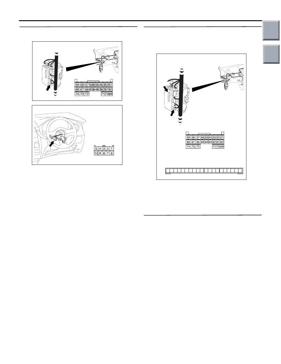
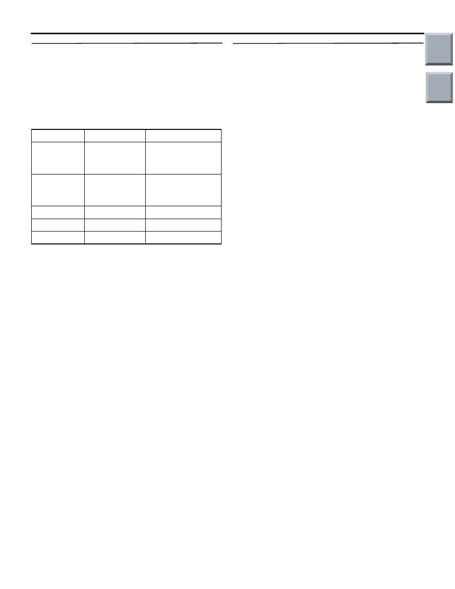
Step 6. Connector check: B-133 ETACS-ECU
connector and B-135 column switch connector
Q: Is the check result normal?
YES :
Go to Step 7.
NO :
Repair the defective connector.
Step 7. Check the wiring harness from B-133
ETACS-ECU connector terminal Nos. 54 and 63 to
B-134 column switch connector terminal Nos. 3
and 2.
• Check the communication lines for open circuit.
Q: Is the check result normal?
YES :
Go to Step 8.
NO :
Repair the wiring harness.
Step 8. ECU check by using the SWS monitor
• Ignition switch: OFF
ECU TO BE CHECKED
• ETACS ECU
OK: "OK" is displayed on the "ETACS ECU"
menu.
Q: Is the check result normal?
YES :
The trouble can be an intermittent
malfunction (Refer to GROUP 00
− How to
use Troubleshooting/inspection Service
Points
− How to Cope with Intermittent
).
NO :
Replace the ETACS-ECU.
AC313826AC
B-133 (GR)
Connector: B-133
Harness side
Junction block (Rear view)
AC401044AC
Connector: B-135
Harness side
AC313827
Connectors: B-133, B-134
AE
B-133 (GR)
B-133
B-134
B-134
13 12
9
10
11
7 6 5
3
4
8
14
2 1
20
17
18
16 15
19
Junction block (Rear view)
Harness side
Junction block side
Main
Index
Group
TOC

SYMPTOM PROCEDURES
SMART WIRING SYSTEM (SWS) USING SWS MONITOR
54C-45
BUZZER
INSPECTION PROCEDURE B-1: Lamp reminder buzzer function does not work normally.
CAUTION
Whenever the ECU is replaced, ensure that the
input and output signal circuits are normal.
COMMENTS ON TROUBLE SYMPTOM
The ETACS-ECU operates this function in accord-
ance with the input signals below.
• Ignition switch (IG1)
• Front door switch (RH)
• Tail lamp switch
• Headlamp switch
If this function does not work normally, these input
signal circuit(s) or the ETACS-ECU may be defec-
tive.
POSSIBLE CAUSES
• Malfunction of the front door switch (RH)
• Malfunction of the column switch
• Malfunction of the ETACS-ECU
• Damaged harness wires and connectors
DIAGNOSTIC PROCEDURE
Step 1. ECU check by using the SWS monitor
Check that the power supply and earth lines to the
ETACS-ECU and the column switch (column-ECU)
and the SWS communication lines are normal.
• Ignition switch: OFF
ECU TO BE CHECKED
• ETACS ECU
• COLUMN ECU
OK: "OK" are displayed for all the items
Q: Is the check result normal?
"OK" is displayed for all the items :
Go to Step 2.
"NG" is displayed on the "ETACS ECU" menu. :
Refer to Inspection Procedure A-3
"Communication with the ETACS-ECU is
not possible
"NG" is displayed on the "COLUMN ECU" menu. :
Refer to Inspection Procedure A-2
"Communication with the column switch
(column-ECU) is not possible
."
ETACS-ECU
INPUT SIGNAL
· DRIVER'S DOOR SWITCH
· TAIL LAMP SWITCH
· IGNITION SWITCH (IG1)
· HEADLAMP SWITCH
Lamp Reminder Tone Alarm Function
Main
Index
Group
TOC
SYMPTOM PROCEDURES
SMART WIRING SYSTEM (SWS) USING SWS MONITOR
54C-46
Step 2. Function diagnosis by using the SWS
monitor
Check the SWS communication signal, which are
related to the lamp reminder function.
<Selected item> BUZZER - LGT MONI. ALRM
• Ignition switch: OFF (key removed)
• lighting switch: TAIL or HEAD
• Driver's door: open
OK: Normal conditions are displayed for all
the items.
Q: Is the check result normal?
Normal conditions are displayed for all the items. :
Go to Step 3.
Normal condition is not displayed for item No.00 or
No.01 :
Refer to inspection procedure N-4
"Column switch (lighting and turn-signal
lamp switch) signal is not received
."
Normal condition is not displayed for item No.30 :
Refer to inspection procedure N-2 "The
ignition switch (IG1) signal is not received
."
Normal condition is not displayed for item No.32 :
Refer to inspection procedure N-3 "The
driver's door switch signal is not received
."
Normal condition is not displayed for item No.43 :
Replace the ETACS-ECU.
Step 3. Retest the system.
The lamp reminder buzzer function should work nor-
mally.
Q: Is the check result normal?
YES :
The trouble can be an intermittent
malfunction (Refer to GROUP 00
− How to
use Troubleshooting/inspection Service
Points
− How to Cope with Intermittent
).
NO :
Replace the ETACS-ECU.
Item No.
Item name
Normal condition
Item 00
HEADLAMP
SW
ON when the
lighting switch is at
HEAD
Item 01
TAIL LAMP SW ON when the
lighting switch is at
TAIL
Item 30
IG SW(IG1)
OFF
Item 32
DR DOOR SW ON
Item 43
BUZZER
ON
Main
Index
Group
TOC

SYMPTOM PROCEDURES
SMART WIRING SYSTEM (SWS) USING SWS MONITOR
54C-47
INSPECTION PROCEDURE B-2: Door-ajar warning buzzer function does not work.
CAUTION
Whenever the ECU is replaced, ensure that the
input and output signal circuits are normal.
NOTE: If the CAN bus diagnostics is carried out, the
door-ajar warning function is triggered.
COMMENTS ON TROUBLE SYMPTOM
The ETACS-ECU operates this function in accord-
ance with the input signals below.
• Ignition switch (IG1)
• All of the door switches
• Vehicle speed signal
If this function does not work normally, these input
signal circuit(s) or the ETACS-ECU may be defec-
tive. Note that this function can be disabled/enabled
by the customise function (default setting; enabled).
In order to change the setting, the SWS monitor is
required.
POSSIBLE CAUSES
• Malfunction of the CAN bus line
• Malfunction of the door switches
• Malfunction of the ETACS-ECU
• Damaged harness wires and connectors
DIAGNOSTIC PROCEDURE
Step 1. Customise function by using the SWS
monitor
Use the SWS monitor customisation function to con-
firm that "DOOR WARN BUZ" is set to "W.FUNC-
TION".
Q: Is the check result normal?
YES :
Go to Step 2.
NO :
Use the SWS monitor customisation
function to set "DOOR WARN BUZ" to
"W.FUNCTION" (Refer to
Step 2. M.U.T.-III CAN bus diagnostics
Use the M.U.T.-III to diagnose the CAN bus lines.
Q: Is the check result normal?
YES :
Go to Step 3.
NO :
Repair the CAN bus line (Refer to GROUP
54D, Diagnosis
Step 3. M.U.T.-III other system diagnosis code
Check whether the combination meter-related diag-
nosis code is set.
Q: Is the diagnosis code set?
YES :
Diagnose the combination meter (Refer to
GROUP 54A
− Troubleshooting
NO :
Go to Step 4.
Door-Ajar Warning Buzzer Function
ETACS-
ECU
SPEED SIGNAL
COMBINATION
METER
CAN COMMUNICATION LINE
(CAN_L LINE)
CAN COMMUNICATION LINE
(CAN_H LINE)
INPUT SIGNAL
INPUT SIGNAL
· DOOR SWITCHES
· IGNITION SWITCH (IG1)
· TAILGATE SWITCH
Main
Index
Group
TOC
Нет комментариевНе стесняйтесь поделиться с нами вашим ценным мнением.
Текст