Mitsubishi Colt Ralliart. Manual — part 50
TROUBLESHOOTING
MULTIPORT FUEL INJECTION (MPI) <4A9>
13A-154
FUNCTION
• Based on the signal from engine-CVT-ECU, the
EGR valve (stepper motor) controls the EGR
rate.
TROUBLE JUDGMENT
Check Conditions
• When the ignition switch is turned to ON position
from OFF position.
or
• EGR valve is in operation after the engine start-
ing process is completed.
Judgment Criterion
• Off-surge voltage is not generated from motor coil
while the EGR valve motor is running.
PROBABLE CAUSES
• Failed EGR valve
• Open/short circuit in EGR valve circuit or loose
connector contact
• Failed engine-CVT-ECU
DIAGNOSIS PROCEDURE
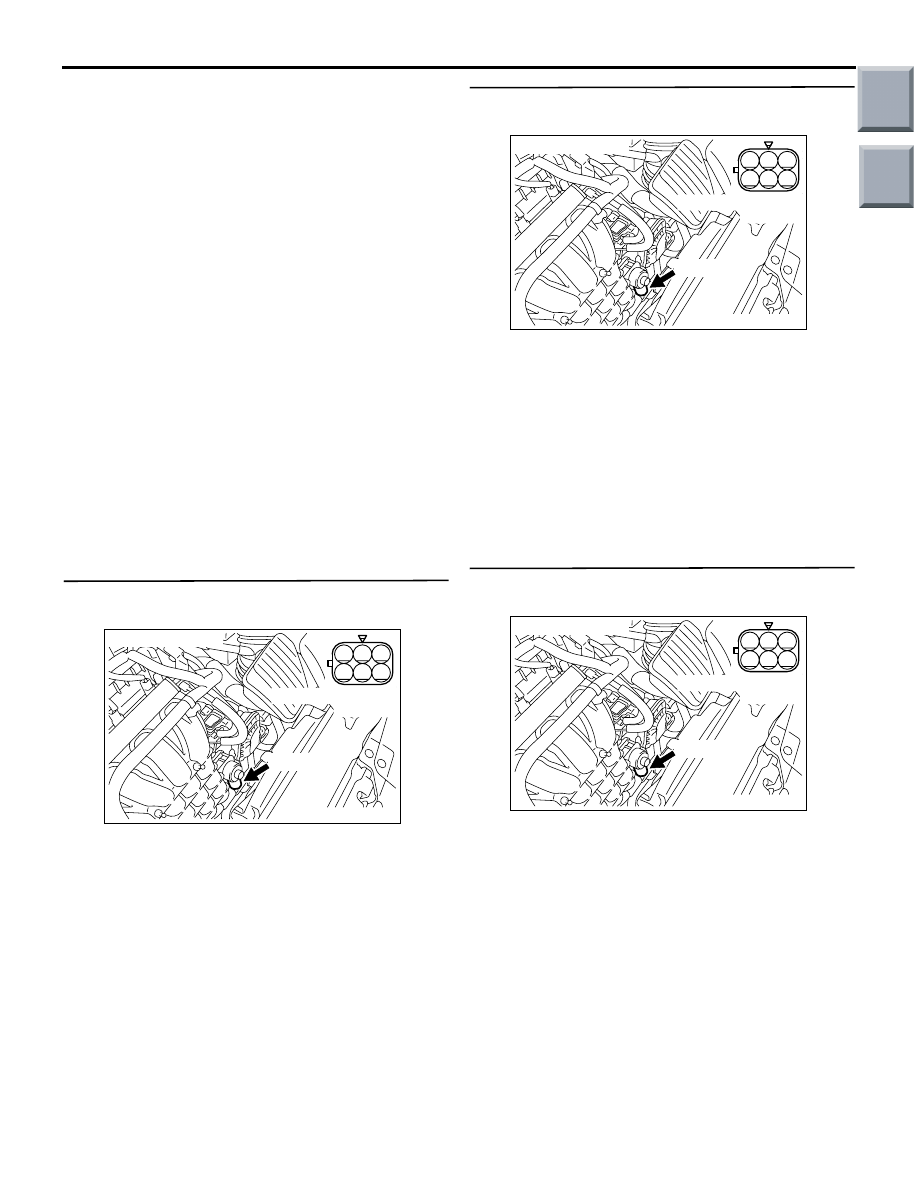
STEP 1. Connector check: A-109 EGR valve
connector
Q: Is the check result normal?
YES :
Go to Step 2 .
NO :
Repair or replace the connector.
STEP 2. Perform resistance measurement at
A-109 EGR valve connector.
• Disconnect connector, and measure at harness
side.
• Resistance between terminal No. 1 and No. 2.
• Resistance between terminal No. 2 and No. 3.
• Resistance between terminal No. 4 and No. 5.
• Resistance between terminal No. 5 and No. 6.
OK: 20
− 24 Ω (at 20°C)
Q: Is the check result normal?
YES :
Go to Step 3 .
NO :
Replace EGR valve.
STEP 3. Perform voltage measurement at A-109
EGR valve connector.
• Disconnect connector, and measure at harness
side.
• Ignition switch: ON
• Voltage between terminal No. 2, No. 5 and earth.
OK: System voltage
Q: Is the check result normal?
YES :
Go to Step 5 .
NO :
Go to Step 4 .
AK402008
3
2 1
6
5 4
AC
Connector: A-109
A-109 (G)
A-109 Harness side
connector
AK402008
3
2 1
6
5 4
AC
Connector: A-109
A-109 (G)
A-109 Harness side
connector
AK402008
3
2 1
6
5 4
AC
Connector: A-109
A-109 (G)
A-109 Harness side
connector
Main
Index
Group
TOC
TROUBLESHOOTING
MULTIPORT FUEL INJECTION (MPI) <4A9>
13A-155
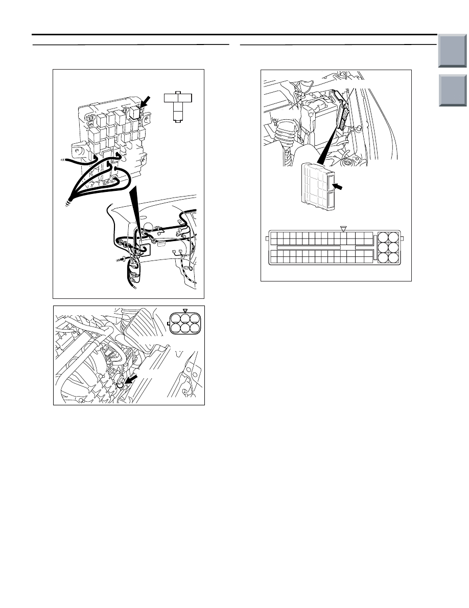
STEP 4. Connector check: B-106 engine control
relay connector
Q: Is the check result normal?
YES :
Check intermediate connector A-17 and
B-112, and repair if necessary. If
intermediate connectors are normal, check
and repair harness between A-109 (terminal
No. 2, No. 5) EGR valve connector and
B-106 (terminal No. 4) engine control relay
connector.
• Check power supply line for
open/short circuit.
NO :
Repair or replace the connector.
STEP 5. Connector check: A-114
engine-CVT-ECU connector
Q: Is the check result normal?
YES :
Go to Step 6 .
NO :
Repair or replace the connector.
3
2
1
4
AK402060
B-106
J/B side
connector
B-106
Connector: B-106
J/B (front side)
AC
AK402008
3
2 1
6
5 4
AC
Connector: A-109
A-109 (G)
A-109 Harness side
connector
AK402745
6
4
2
5
3
1
9
7
8
10
11
12
13
14
15
16
17
18
19
20
21
22
23
24
25
26
27
28
29
30
31
32
33
34
35
36
37
38
39
40
41
42
43
44
45
46
47
48
49
50
51
52
53
54
55
56
57
58
59
60
61
62
63
64
65
66
L
AB
A-114
Connector:
A-114
Harness side connector
Engine-CVT-ECU
Battery
Main
Index
Group
TOC
TROUBLESHOOTING
MULTIPORT FUEL INJECTION (MPI) <4A9>
13A-156
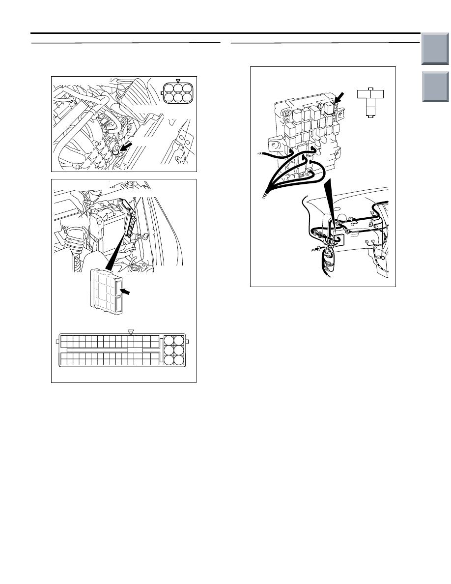
STEP 6. Check harness between A-109 EGR
valve connector and A-114 engine-CVT-ECU
connector.
a. Check harness between A-109 (terminal No. 1)
EGR valve and A-114 (terminal No. 5)
engine-CVT-ECU connector.
b. Check harness between A-109 (terminal No. 3)
EGR valve and A-114 (terminal No. 6)
engine-CVT-ECU connector.
c. Check harness between A-109 (terminal No. 4)
EGR valve and A-114 (terminal No. 53)
engine-CVT-ECU connector.
d. Check harness between A-109 (terminal No. 6)
EGR valve and A-114 (terminal No. 54)
engine-CVT-ECU connector.
• Check output line for open/short circuit and dam-
age.
Q: Are the check results normal?
YES :
Go to Step 7 .
NO :
Repair the damaged harness wire.
STEP 7. Connector check: B-106 engine control
relay connector
Q: Is the check result normal?
YES :
Go to Step 8 .
NO :
Repair or replace the connector.
AK402008
3
2 1
6
5 4
AC
Connector: A-109
A-109 (G)
A-109 Harness side
connector
AK402745
6
4
2
5
3
1
9
7
8
10
11
12
13
14
15
16
17
18
19
20
21
22
23
24
25
26
27
28
29
30
31
32
33
34
35
36
37
38
39
40
41
42
43
44
45
46
47
48
49
50
51
52
53
54
55
56
57
58
59
60
61
62
63
64
65
66
L
AB
A-114
Connector:
A-114
Harness side connector
Engine-CVT-ECU
Battery
3
2
1
4
AK402060
B-106
J/B side
connector
B-106
Connector: B-106
J/B (front side)
AC
Main
Index
Group
TOC

TROUBLESHOOTING
MULTIPORT FUEL INJECTION (MPI) <4A9>
13A-157
STEP 8. Check harness between A-109 (terminal
No. 2, No. 5) EGR valve connector and B-106
(terminal No. 4) engine control relay connector.
NOTE: Before checking harness, check intermediate
connector A-17 and B-112, and repair if necessary.
• Check power supply line for damage.
Q: Is the check result normal?
YES :
Go to Step 9 .
NO :
Repair the damaged harness wire.
STEP 9. M.U.T.-III diagnosis code
• Reconfirmation of diagnosis code.
Q: Is the diagnosis code set?
YES :
Replace engine-CVT-ECU.
NO :
Intermittent malfunction (Refer to GROUP
00
− How to Use Troubleshooting/Inspection
Service Points
− How to Cope with
Intermittent Malfunctions
).
AK402008
3
2 1
6
5 4
AC
Connector: A-109
A-109 (G)
A-109 Harness side
connector
3
2
1
4
AK402060
B-106
J/B side
connector
B-106
Connector: B-106
J/B (front side)
AC
Main
Index
Group
TOC
Нет комментариевНе стесняйтесь поделиться с нами вашим ценным мнением.
Текст