Mitsubishi Colt Ralliart. Manual — part 51

TROUBLESHOOTING
MULTIPORT FUEL INJECTION (MPI) <4A9>
13A-158
Code No. P0421: Warm Up Catalyst Malfunction
FUNCTION
• The signal from the oxygen sensor (rear) differs
from the oxygen sensor (front). That is because
the catalytic converter purifies exhaust gas.
When the catalytic converter has deteriorated,
the signal from the oxygen sensor (front)
becomes similar to the oxygen sensor (rear).
• The engine-ECU <M/T> or engine-CVT-ECU
<CVT> compares the output of the oxygen sen-
sor signals (front and rear).
TROUBLE JUDGMENT
Check Conditions
• Engine speed is 3,000 r/min or lower.
• The accelerator pedal is open.
• 3 seconds or more elapsed after the above men-
tioned conditions were satisfied.
• Under the closed loop air/fuel ratio control.
• Vehicle speed is 1.5 km/h or higher.
• For 10 seconds per cycle, the engine-ECU
<M/T> or engine-CVT-ECU <CVT> monitors 7
cycles of this condition during the drive cycle.
• Short-term fuel trim is between −25 % or higher
and +25 % or lower.
Judgment Criterion
• The oxygen sensor (rear) signal frequency
divided by oxygen sensor (front) signal frequency
is 0.8 or more.
PROBABLE CAUSES
• Catalytic converter deteriorated
• Failed oxygen sensor (front)
• Failed oxygen sensor (rear)
• Failed engine-ECU <M/T> or engine-CVT-ECU
<CVT>
DIAGNOSIS PROCEDURE
STEP 1. Check for leakage of exhaust emission
from exhaust manifold.
Q: Is the check result normal?
YES :
Go to Step 2 .
NO :
Repair.
STEP 2. M.U.T.-III data list
• Refer to Data List Reference Table
.
a. Item 11: Oxygen sensor (front)
b. Item 59: Oxygen sensor (rear)
Q: Are the check results normal?
YES :
Go to Step 3 .
NO :
Perform the diagnosis code classified check
procedure for the sensor that has shown an
abnormal data valve (Refer to Inspection
Chart for Diagnosis Code
STEP 3. M.U.T.-III data list
• Item 11: Oxygen sensor (front)
OK: 0
− 0.4 and 0.6 − 1.0 volt should alternate
15 times or more within 10 seconds (engine
speed at 2,000 r/min).
Q: Is the check result normal?
YES :
Go to Step 4 .
NO :
Replace the oxygen sensor (front).
STEP 4. Replace the oxygen sensor (rear).
• After replacing the oxygen sensor (rear),
re-check the trouble symptoms.
Q: Is the check result normal?
YES :
Check end.
NO :
Go to Step 5 .
STEP 5. Replace the catalytic converter.
• After replacing the catalytic converter, re-check
the trouble symptoms.
Q: Is the check result normal?
YES :
Replace engine-ECU <M/T> or
engine-CVT-ECU <CVT>.
NO :
Check end.
Main
Index
Group
TOC
TROUBLESHOOTING
MULTIPORT FUEL INJECTION (MPI) <4A9>
13A-159
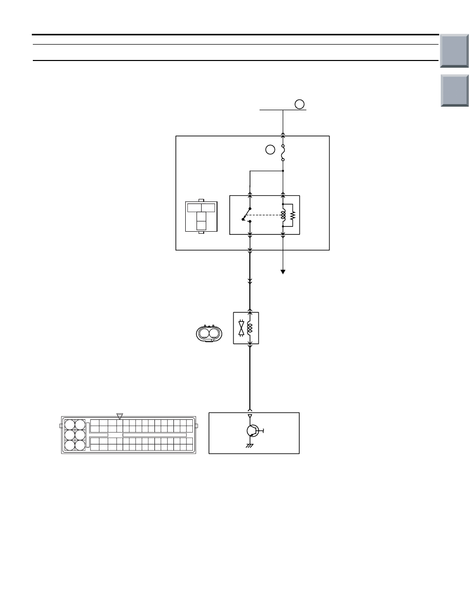
Code No. P0443: Purge Control Solenoid Valve System
OPERATION
• Power is supplied to the purge control solenoid
valve (terminal No. 2) from the engine control
relay (terminal No. 4).
• The engine-ECU <M/T> or engine-CVT-ECU
<CVT> (terminal No. 38) makes the power tran-
sistor in the unit be in ON position, and that
makes currents go on the purge control solenoid
valve (terminal No. 1).
AK402707
3
1
2
4
1 2
19
21
20
18
17
16
15
14
1213
11
8 9
L
10
37
52 53 54 555657585960616263646566
38 39 404142434445464748495051
22 23 24 252627282930313233343536
7
5
3
1
6
4
2
Engine
control
relay
B-106
4
2
38
Engine-ECU <M/T> or
engine-CVT-ECU <CVT>
To engine-ECU <M/T> or
engine-CVT-ECU <CVT>
A-108
MU802779
B-112
A-17
B-108
Purge control
solenoid valve
1
2
4
6
Purge Control Solenoid Valve Circuit
R
R
L-R
3
1
A-114
1
1
R
Fusible link
16
20A
J/B
AC
Wire colour code
B: Black LG: Light green G: Green L: Blue W: White Y: Yellow SB: Sky blue BR: Brown O: Orange GR: Gray
R: Red P: Pink V: Violet Pu: Purple
Main
Index
Group
TOC

TROUBLESHOOTING
MULTIPORT FUEL INJECTION (MPI) <4A9>
13A-160
FUNCTION
• In response to a signal from the engine-ECU
<M/T> or engine-CVT-ECU <CVT>, the purge
control solenoid valve controls the flow rate of the
purge air to be introduced into the surge tank.
TROUBLE JUDGMENT
Check Conditions
• Engine is running <M/T>.
• Battery positive voltage is more than 10 V and is
less than 16 V <M/T>.
• Engine speed is more than 1,200 r/min and is
less than 3,000 r/min <M/T>.
• Ignition switch is in ON position <CVT>.
• Battery positive voltage is 10 V or higher <CVT>.
Judgment Criterion
• The surge voltage (system voltage +2 V) of sole-
noid coil is not detected when the purge control
solenoid valve is turned in OFF position from ON.
PROBABLE CAUSES
• Failed purge control solenoid valve
• Open/short circuit in purge control solenoid value
circuit or loose connector contact
• Failed engine-ECU <M/T> or engine-CVT-ECU
<CVT>
DIAGNOSIS PROCEDURE
STEP 1. M.U.T.-III actuator test
• Item 08: Purge control solenoid valve
OK: Operating sound can be heard and the
valve vibrates
Q: Is the check result normal?
YES :
Intermittent malfunction (Refer to GROUP
00
− How to Use
Troubleshooting/Inspection Service Points
−
How to Cope with Intermittent Malfunctions
).
NO :
Go to Step 2 .
STEP 2. Connector check: A-108 purge control
solenoid valve connector
Q: Is the check result normal?
YES :
Go to Step 3 .
NO :
Repair or replace the connector.
STEP 3. Perform resistance measurement at
A-108 purge control solenoid valve connector.
• Disconnect connector, and measure at solenoid
valve side.
• Resistance between terminal No. 1 and No. 2.
OK: 30
− 34 Ω (at 20°C)
Q: Is the check result normal?
YES :
Go to Step 4 .
NO :
Replace purge control solenoid valve.
AK402007
1
2
AC
Connector: A-108
A-108 (B)
A-108 Harness side
connector
AK402007
1
2
AC
Connector: A-108
A-108 (B)
A-108 Harness side
connector
Main
Index
Group
TOC

TROUBLESHOOTING
MULTIPORT FUEL INJECTION (MPI) <4A9>
13A-161
STEP 4. Perform voltage measurement at A-108
purge control solenoid valve connector.
• Disconnect connector, and measure at harness
side.
• Ignition switch: ON
• Voltage between terminal No. 2 and earth.
OK: System voltage
Q: Is the check result normal?
YES :
Go to Step 6 .
NO :
Go to Step 5 .
STEP 5. Connector check: B-106 engine control
relay connector
Q: Is the check result normal?
YES :
Check intermediate connector A-17 and
B-112, and repair if necessary. If
intermediate connector is normal, check and
repair harness between A-108 (terminal No.
2) purge control solenoid valve connector
and B-106 (terminal No. 4) engine control
relay connector.
• Check power line for open/short
circuit.
NO :
Repair or replace the connector.
AK402007
1
2
AC
Connector: A-108
A-108 (B)
A-108 Harness side
connector
3
2
1
4
AK402060
B-106
J/B side
connector
B-106
Connector: B-106
J/B (front side)
AC
AK402007
1
2
AC
Connector: A-108
A-108 (B)
A-108 Harness side
connector
Main
Index
Group
TOC
Нет комментариевНе стесняйтесь поделиться с нами вашим ценным мнением.
Текст