Mitsubishi Colt Ralliart. Manual — part 605

FUEL AND EMISSION PARTS
ENGINE OVERHAUL <4G1>
11D-20
FUEL AND EMISSION PARTS
REMOVAL AND INSTALLATION
M1113002201251
AK401837AC
9.0 ± 1.0 N·m
1
16
15
14
12
13
11
10
8
7
6
5
4
3
2
5.0 ± 1.0 N·m
9
12 ± 1 N·m
18
17
9.0 ± 1.0 N·m
5.0 ± 1.0 N·m
13 ± 2 N·m
Removal steps
1. Water hose
2. Water hose
3. Throttle body
>>
B
<< 4. Throttle body gasket
5. Vacuum hose
6. Vacuum hose
7. Solenoid valve
8. Purge valve
9. Delivery pipe and injector
10. Insulator
11. Insulator
12. O-ring
>>
A
<< 13. Injector
14. Fuel hose
15. Fuel pressure regulator
>>
A
<< 16. Delivery pipe
17. Vacuum pipe and hose
18. Solenoid valve
Removal steps (Continued)
Main
Index
Group
TOC
FUEL AND EMISSION PARTS
ENGINE OVERHAUL <4G1>
11D-21
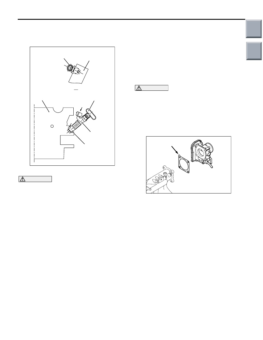
INSTALLATION SERVICE POINTS
>>A<< INJECTOR/DELIVERY PIPE
INSTALLATION
AK201877
Delivery pipe
Injector
Injector
Insulator
Cylinder head
A
A
AF
Delivery pipe
1. Fit the insulator onto the injector.
CAUTION
Take care that no engine oil enters the delivery
pipe.
2. Apply a little fresh engine oil to the injector O-ring.
Then, insert the injector, center to center, into the
injector mounting hole on the delivery pipe.
3. Make sure that the injector connector projection is
properly engaged with the delivery pipe.
Turn the injector to ensure engagement if
necessary.
4. Check that the injector rotates smoothly. If it does
not, remove it and check the injector O-ring for
damage. If damage is evident, replace the O-ring,
reinstall the injector to the delivery pipe and check
it again for smooth rotation.
5. Install the delivery pipe to the cylinder head.
CAUTION
Connect the injector securely, having no air leak-
age from the insulator.
6. Install the insulator, connecting securely to the
injector without the clearance.
>>B<< THROTTLE BODY GASKET
INSTALLATION
AK401855
AC
Projection
Install the throttle body gasket, facing the gasket’s
protruded portion in the illustrated position.
Main
Index
Group
TOC

WATER PUMP AND WATER HOSE
ENGINE OVERHAUL <4G1>
11D-22
WATER PUMP AND WATER HOSE
REMOVAL AND INSTALLATION
M1113017900468
AK401836AC
22 ± 4 N·m
1
14 ± 1 N·m
13 ± 2 N·m
13 ± 2 N·m
29 ± 10 N·m
13 ± 2 N·m
10 ± 2 N·m
2
3
4
10
9
8
7
6
5
11
14
13
12
Removal steps
>>
C
<< 1. Engine coolant temperature sensor
2. Water inlet fitting
>>
B
<< 3. Thermostat
4. Water hose
5. Water hose
6. Water hose
7. Water hose
8. Water hose
9. Water hose
10. Water pipe
>>
A
<< 11. Water inlet pipe
>>
A
<< 12. O-ring
>>
A
<< 13. O-ring
14. Water pump
Removal steps (Continued)
Main
Index
Group
TOC

WATER PUMP AND WATER HOSE
ENGINE OVERHAUL <4G1>
11D-23
INSTALLATION SERVICE POINTS
>>A<< O-RING/WATER INLET PIPE
INSTALLATION
CAUTION
• Do not apply engine oil or any other oily sub-
stance to the O-rings.
• Secure the water pipe after the thermostat
case has been installed.
Replace the water inlet pipe O-rings with new ones,
then apply water to the O-rings so that they can be
inserted easily into the water pump and thermostat
case.
>>B<< THERMOSTAT INSTALLATION
AK201781 AC
Jiggle valve
Install the thermostat to the thermostat housing so
that its jiggle valve can locate around the center.
>>C<< ENGINE COOLANT
TEMPERATURE SENSOR INSTALLATION
CAUTION
Take care not to damage the connector (plastic)
with tool.
AK400587AD
1. Completely remove existing sealant from the
engine coolant temperature sensor and mating
hole in the thermostat housing.
2. Apply the specified sealant to the threads of the
sensor.
Specified sealant:
3M Nut Locking Part No.4171 or equivalent
3. Tighten the water temperature sensor together
with the thermostat housing to the specified
torque of 29
± 10 N⋅m.
Main
Index
Group
TOC
Нет комментариевНе стесняйтесь поделиться с нами вашим ценным мнением.
Текст