Mitsubishi Colt Ralliart. Manual — part 569
TROUBLESHOOTING
SUPPLEMENTAL RESTRAINT SYSTEM (SRS)
52B-114
Q: Is the check result normal?
YES :
Go to Step 3.
NO :
Repair the harness wires between
SRS-ECU connector B-34 (terminal No.23
and 24) and side-airbag module (RH)
connector C-25 (terminal No.1 and 2).
STEP 3. Check whether the diagnosis code is
reset.
Q: Is diagnosis code 76 set?
YES :
Replace the SRS-ECU (Refer to
).
NO :
An intermittent malfunction is suspected
(Refer to GROUP 00, How to Cope with
Intermittent Malfunction
).
Code No.79: Side impact sensor (LH) communication error
Code No.93: Side impact sensor (LH) communication impossible
OPERATION
The side impact sensor (front) includes an analogue
G-sensor and CPU, etc. The CPU monitors the ana-
logue G-sensor output signal. If the CPU judges that
the side-airbags should be deployed, it sends a fire
signal to the SRS-ECU to deploy the side-airbags.
Besides that, the CPU diagnoses the internal compo-
nents of the side impact sensor. If a malfunction
occurs, it requests the SRS-ECU to set a diagnosis
code.
DIAGNOSIS CODE SET CONDITIONS
These diagnosis codes are set if communication
between the side impact sensor (LH) and the
SRS-ECU is not possible or communication is faulty.
PROBABLE CAUSES
• Damaged wiring harnesses or connectors
• Malfunction of the side impact sensor (LH)
• Malfunction of the SRS-ECU
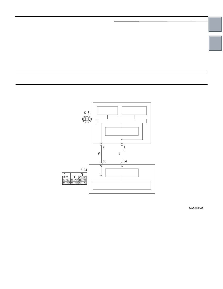
AC510245
SRS-ECU
CONSTANT
VOLTAGE CIRCUIT
ANALOGUE
G SENSOR
EEP ROM
SIDE IMPACT
SENSOR (LH)
MICRO COMPUTER
INTERFACE
CIRCUIT
CPU
Wire colour code
B : Black LG : Light green G : Green L : Blue W : White Y : Yellow SB : Sky blue
BR : Brown O : Orange GR : Grey R : Red P : Pink V : Violet
Side Impact Sensor (LH) Power Supply Circuit
AB
Main
Index
Group
TOC
TROUBLESHOOTING
SUPPLEMENTAL RESTRAINT SYSTEM (SRS)
52B-115
DIAGNOSIS PROCEDURE
STEP 1. Check the side impact sensor (LH).
(M.U.T.-III diagnosis code)
(1) Disconnect the negative battery terminal.
(2) Temporarily replace the side impact sensor (LH)
with the side impact sensor (RH).
(3) Connect the negative battery terminal.
(4) Erase diagnosis code memory, and check the
diagnosis code.
Q: Is diagnosis code 89 or 96 set?
YES :
Replace the side impact sensor (LH) with a
new one (Refer to
).
NO :
Go to Step 2.
STEP 2. Check the harness wires for open circuit
or short circuit between SRS-ECU connector
B-34 (terminal No.34 and 36) and side impact
sensor (LH) (front) connector C-21 (terminal No.1
and 2).
Q: Is the check result normal?
YES :
Go to Step 3.
NO :
Repair the harness wires between
SRS-ECU connector B-34 (terminal No.34
and 36) and side impact sensor (LH)
connector C-21 (terminal No.1 and 2).
STEP 3. Check whether the diagnosis code is
reset.
Q: Is diagnosis code 79 or 93 set?
YES :
Replace the SRS-ECU (Refer to
).
NO :
An intermittent malfunction is suspected
(Refer to GROUP 00, How to Cope with
Intermittent Malfunction
).
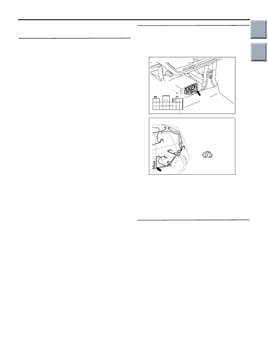
AC206285
AG
B-34 (Y)
Connector: B-34
Harness side
connector
(rear view)
343536373839404142
252627282930313233
2122
2324
AC401059
Connector: C-21
AF
C-21 (Y)
Harness side
(front view)
Main
Index
Group
TOC
TROUBLESHOOTING
SUPPLEMENTAL RESTRAINT SYSTEM (SRS)
52B-116
Code No.81: Side-airbag module (squib) (LH) system (short-circuited between terminals of the squib
circuit)
OPERATION
• The SRS-ECU judges how severe a collision is
by detecting signals from the left and right side
impact sensors. If the impact is over a predeter-
mined level, the SRS-ECU sends an ignition sig-
nal. At this time, if the side-airbag safing
G-sensor is on, the SRS side-airbag will inflate.
• The ignition signal is input to the side-airbag
module to inflate the side-airbag.
DIAGNOSIS CODE SET CONDITIONS
This diagnosis code is set if one side-airbag squib
(LH) wire shorted to the other. However, if no diagno-
sis code resets, the SRS warning lamp will be
switched off (diagnosis code will be retained).
PROBABLE CAUSES
• Improper engaged connector or defective short
spring*
• Short circuit between the side-airbag module
(LH) (squib) circuit terminals
• Damaged connector(s)
• Malfunction of the SRS-ECU
NOTE: *: The squib circuit connectors integrate a
"short" spring (which prevents the air bag from
deploying unintentionally due to static electricity by
shorting the positive wire to the earth wire in the
squib circuit when the connectors are disconnected).
(Refer to
). Therefore, if connector B-34 or
C-23 is damaged or improperly engaged, the short
spring may not be released when the connector is
connected.
DIAGNOSIS PROCEDURE
STEP 1. M.U.T.-III diagnosis code
Q: Is diagnosis code 34 set?
YES :
Go to Step 2.
NO :
Go to Step 3.
AC510246
AIR BAG DRIVE
CIRCUIT
MICRO COMPUTER
SRS-ECU
SIDE-AIRBAG
MODULE
(SQUIB)
(LH)
Wire colour code
B : Black LG : Light green
G : Green L : Blue
W : White Y : Yellow
SB : Sky blue BR : Brown
O : Orange GR : Grey
R : Red P : Pink V : Violet
NOTE
CONNECTOR
COUPLED: ON
CONNECTOR
UNCOUPLED: OFF
CONNECTOR
LOCK
SWITCH
CONNECTOR
LOCK
SWITCH
Side-airbag Module (LH) (Squib) Circuit
AB
Main
Index
Group
TOC
TROUBLESHOOTING
SUPPLEMENTAL RESTRAINT SYSTEM (SRS)
52B-117
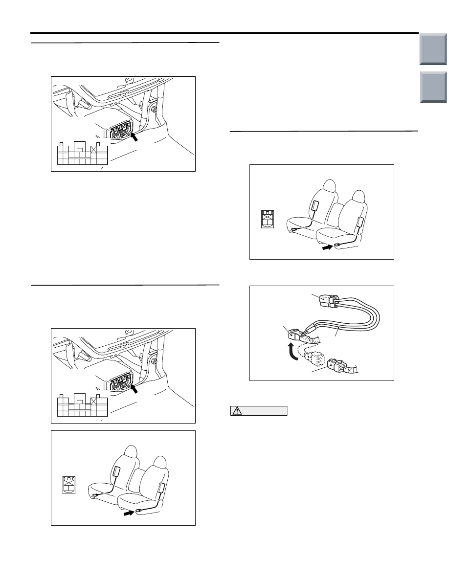
STEP 2. Connector lock check: SRS-ECU
connector B-34 (M.U.T.-III diagnosis code)
(1) Disconnect the negative battery terminal.
(2) Disconnect connectors B-34 and then reconnect
them.
(3) Connect the negative battery terminal.
(4) Erase the diagnosis code memory, and check the
diagnosis code.
Q: Is diagnosis code 81 out put?
YES :
Go to Step 3.
NO :
The procedure is complete. It is assumed
that diagnosis code 81 set as connector
B-34 was engaged improperly.
STEP 3. Connector lock check: SRS-ECU
connector B-34 and side-airbag module (LH)
connector C-23 (M.U.T.-III diagnosis code)
(1) Disconnect the negative battery terminal.
(2) Disconnect connectors B-34 and C-23 and then
reconnect them.
(3) Connect the negative battery terminal.
(4) Erase the diagnosis code memory, and check the
diagnosis code.
Q: Is diagnosis code 81 out put?
YES :
Go to Step 4.
NO :
The procedure is complete. It is assumed
that diagnosis code 81 set as connector
B-34 or C-23 was engaged improperly.
STEP 4. Check the diagnosis code by connecting
a dummy resistor. (M.U.T.-III diagnosis code)
(1) Disconnect the negative battery terminal.
(2) Disconnect the side-airbag module (LH)
connector C-23.
(3) Connect special tool dummy resistor (MB991865)
to special tool resistor harness (MB991866).
CAUTION
Do not insert a test probe into the terminal from
its front side directly as the connector contact
pressure may be weakened.
(4) Insert special tool (MB991866) into the C-23
harness side connector by backprobing.
(5) Connect the negative battery terminal.
(6) Erase diagnosis code memory, and check the
diagnosis code.
Q: Is diagnosis code 81 set?
YES :
Go to Step 5.
NO :
Replace the frame assembly of the front
seat (LH) (Refer to GROUP 52A, Front Seat
).
AC206285
AG
B-34 (Y)
Connector: B-34
Harness side
connector
(rear view)
343536373839404142
252627282930313233
2122
2324
AC206285
AG
B-34 (Y)
Connector: B-34
Harness side
connector
(rear view)
343536373839404142
252627282930313233
2122
2324
AC401575
Connector: C-23
AC
C-23 (R)
2 1
Harness side
connector
(front view)
AC401575
Connector: C-23
AC
C-23 (R)
2 1
Harness side
connector
(front view)
AC006042 CM
MB991866
(Resistor harness)
C-23
Intermediate h
arness side
connector
MB991865 (Dummy
resistor: 3
Ω)
C-23 Side-airbag
module (LH) connector
Main
Index
Group
TOC
Нет комментариевНе стесняйтесь поделиться с нами вашим ценным мнением.
Текст