Mitsubishi Colt Ralliart. Manual — part 570
TROUBLESHOOTING
SUPPLEMENTAL RESTRAINT SYSTEM (SRS)
52B-118
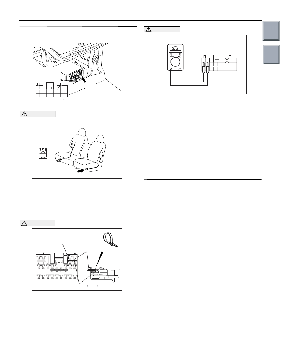
STEP 5. Resistance measurement at the
SRS-ECU connector B-34
(1) Disconnect SRS-ECU connector B-34.
DANGER
To prevents the air bag from deploying unin-
tentionally, disconnect the side-airbag mod-
ule (LH) connector C-23 to short the squib
circuit.
(2) Disconnect left hand side-airbag module (LH)
connector C-23.
CAUTION
Insert an insulator such as a cable tie to a depth
of 4mm or more, otherwise the short spring will
not be released.
(3) Insert a cable tie [3 mm wide, 0.5 mm thick]
between terminals 21, 22 and the short spring to
release the short spring.
CAUTION
Do not insert a test probe into the terminal from
its front side directly as the connector contact
pressure may be weakened.
(4) Check for continuity between B-34 harness side
connector terminals 21 and 22
OK: Open circuit
Q: Is the check result normal?
YES :
Go to Step 6.
NO :
Repair the harness wires between
SRS-ECU connector B-34 (terminal No.21
and 22) and side-airbag module (LH)
connector C-23 (terminal No.1 and 2).
STEP 6. Check whether the diagnosis code is
reset.
Q: Is diagnosis code 81 set?
YES :
Replace the SRS-ECU (Refer to
).
NO :
An intermittent malfunction is suspected
(Refer to GROUP 00, How to Cope with
Intermittent Malfunction
).
AC206285
AG
B-34 (Y)
Connector: B-34
Harness side
connector
(rear view)
343536373839404142
252627282930313233
2122
2324
AC401575
Connector: C-23
AC
C-23 (R)
2 1
Harness side
connector
(front view)
AC100397
Section
A - A
B-34 Harness side connector
(front view)
Cable tie
Short spring
4 mm or more
Terminal
A
AV
A
34 35 36 37 38 39 40 41 42
25 26 27 28 29 30 31 32 33
21 22
23 24
AC100386
B-34 Harness side connector
(rear view)
AQ
Main
Index
Group
TOC
TROUBLESHOOTING
SUPPLEMENTAL RESTRAINT SYSTEM (SRS)
52B-119
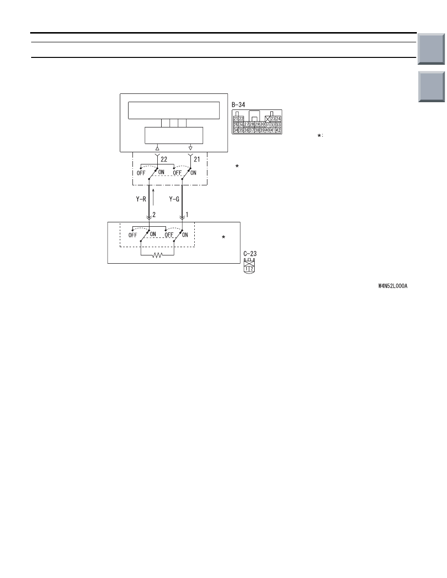
Code No.82: Side-airbag module (squib) (LH) system (open-circuited in the squib circuit)
OPERATION
• The SRS-ECU judges how severe a collision is
by detecting signals from the left and right side
impact sensors. If the impact is over a predeter-
mined level, the SRS-ECU sends an ignition sig-
nal. At this time, if the side-airbag safing
G-sensor is on, the SRS side-airbag will inflate.
• The ignition signal is input to the side-airbag
module to inflate the side-airbag.
DIAGNOSIS CODE SET CONDITIONS
This diagnosis code is set if the side-airbag squib
(LH) wire(s) are open-circuited. However, if no diag-
nosis code resets, the SRS warning lamp will be
switched off (diagnosis code will be retained).
PROBABLE CAUSES
• Open circuit in the side-airbag module (squib)
(LH) circuit
• Improper connector contact
• Malfunction of the SRS-ECU
AC510246
AIR BAG DRIVE
CIRCUIT
MICRO COMPUTER
SRS-ECU
SIDE-AIRBAG
MODULE
(SQUIB)
(LH)
Wire colour code
B : Black LG : Light green
G : Green L : Blue
W : White Y : Yellow
SB : Sky blue BR : Brown
O : Orange GR : Grey
R : Red P : Pink V : Violet
NOTE
CONNECTOR
COUPLED: ON
CONNECTOR
UNCOUPLED: OFF
CONNECTOR
LOCK
SWITCH
CONNECTOR
LOCK
SWITCH
Side-airbag Module (LH) (Squib) Circuit
AB
Main
Index
Group
TOC
TROUBLESHOOTING
SUPPLEMENTAL RESTRAINT SYSTEM (SRS)
52B-120
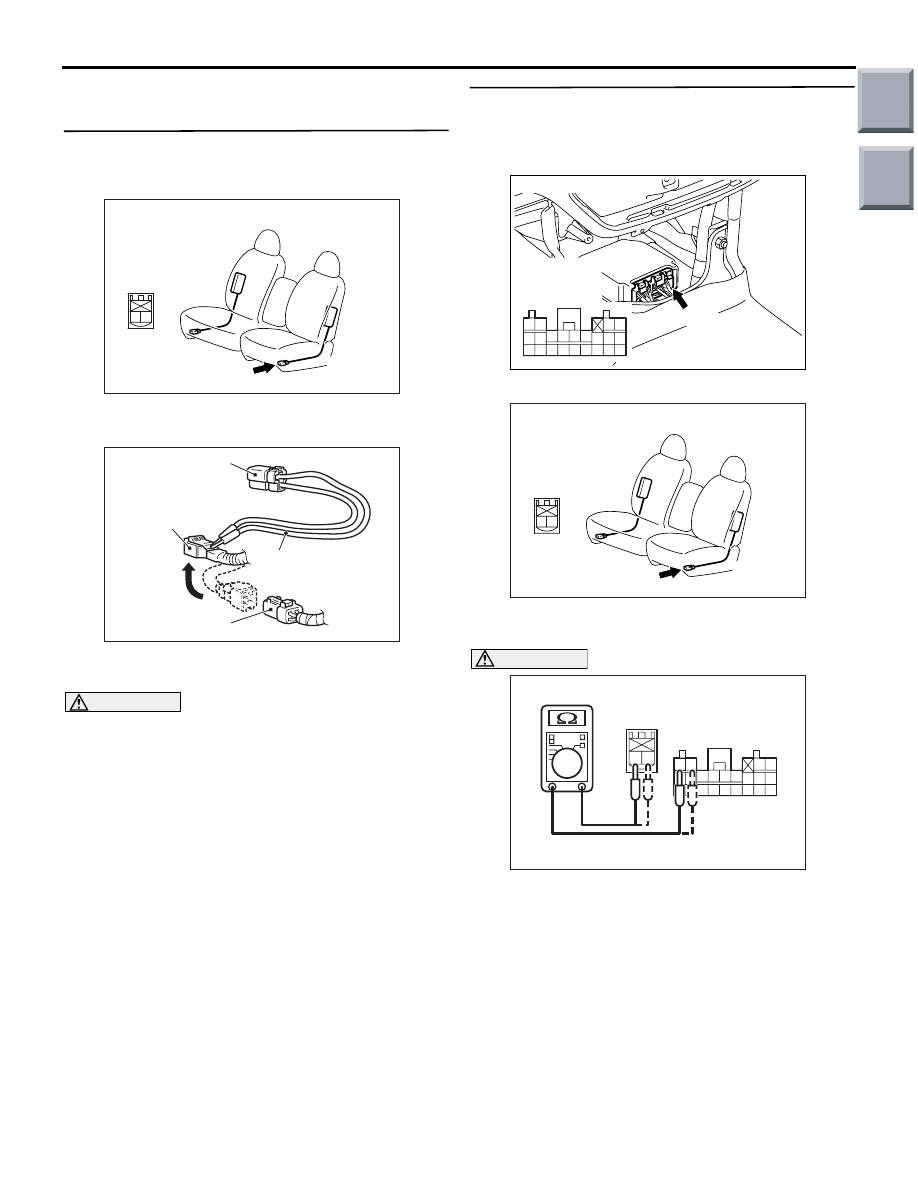
DIAGNOSIS PROCEDURE
STEP 1. Check the diagnosis code by connecting
a dummy resistor. (M.U.T.-III diagnosis code)
(1) Disconnect the negative battery terminal.
(2) Disconnect the side-airbag module (LH)
connector C-23.
(3) Connect special tool dummy resistor (MB991865)
to special tool resistor harness (MB991866).
CAUTION
Do not insert a test probe into the terminal from
its front side directly as the connector contact
pressure may be weakened.
(4) Insert special tool (MB991866) into the C-23
harness side connector by backprobing.
(5) Connect the negative battery terminal.
(6) Erase diagnosis code memory, and then check
the diagnosis code.
Q: Is diagnosis code 82 set?
YES :
Go to Step 2.
NO :
Replace the frame assembly of the front
seat (LH) (Refer to GROUP 52A, Front Seat
).
STEP 2. Resistance measurement between the
SRS-ECU connector B-34 (terminal No.21 and 22)
and the side-airbag module (LH) connector C-23
(terminal No.1 and 2)
(1) Disconnect SRS-ECU connector B-34.
(2) Disconnect side-airbag module (LH) connector
C-23.
CAUTION
Do not insert a test probe into the terminal from
its front side directly as the connector contact
pressure may be weakened.
(3) Resistance measurement between the following
terminals.
• SRS-ECU connector B-34 (terminal No.21)
and the side-airbag module (LH) connector
C-23 (terminal No.1)
• SRS-ECU connector B-34 (terminal No.22)
and the side-airbag module (LH) connector
C-23 (terminal No.2)
OK: Continuity (Less than 2
Ω)
AC401575
Connector: C-23
AC
C-23 (R)
2 1
Harness side
connector
(front view)
AC006042 CM
MB991866
(Resistor harness)
C-23
Intermediate h
arness side
connector
MB991865 (Dummy
resistor: 3
Ω)
C-23 Side-airbag
module (LH) connector
AC206285
AG
B-34 (Y)
Connector: B-34
Harness side
connector
(rear view)
343536373839404142
252627282930313233
2122
2324
AC401575
Connector: C-23
AC
C-23 (R)
2 1
Harness side
connector
(front view)
343536373839404142
252627282930313233
2122
2324
1 2
AC100387
B-34 Harness
side connector
(rear view)
AL
C-23 Harness side
connector
(rear view)
Main
Index
Group
TOC
TROUBLESHOOTING
SUPPLEMENTAL RESTRAINT SYSTEM (SRS)
52B-121
Q: Are the check results normal?
YES :
Go to Step 3.
NO :
Repair the harness wires between
SRS-ECU connector B-34 (terminal No.21
and 22) and side-airbag module (LH)
connector C-23 (terminal No.1 and 2).
STEP 3. Check whether the diagnosis code is
reset.
Q: Is diagnosis code 82 set?
YES :
Replace the SRS-ECU (Refer to
).
NO :
An intermittent malfunction is suspected
(Refer to GROUP 00, How to Cope with
Intermittent Malfunction
).
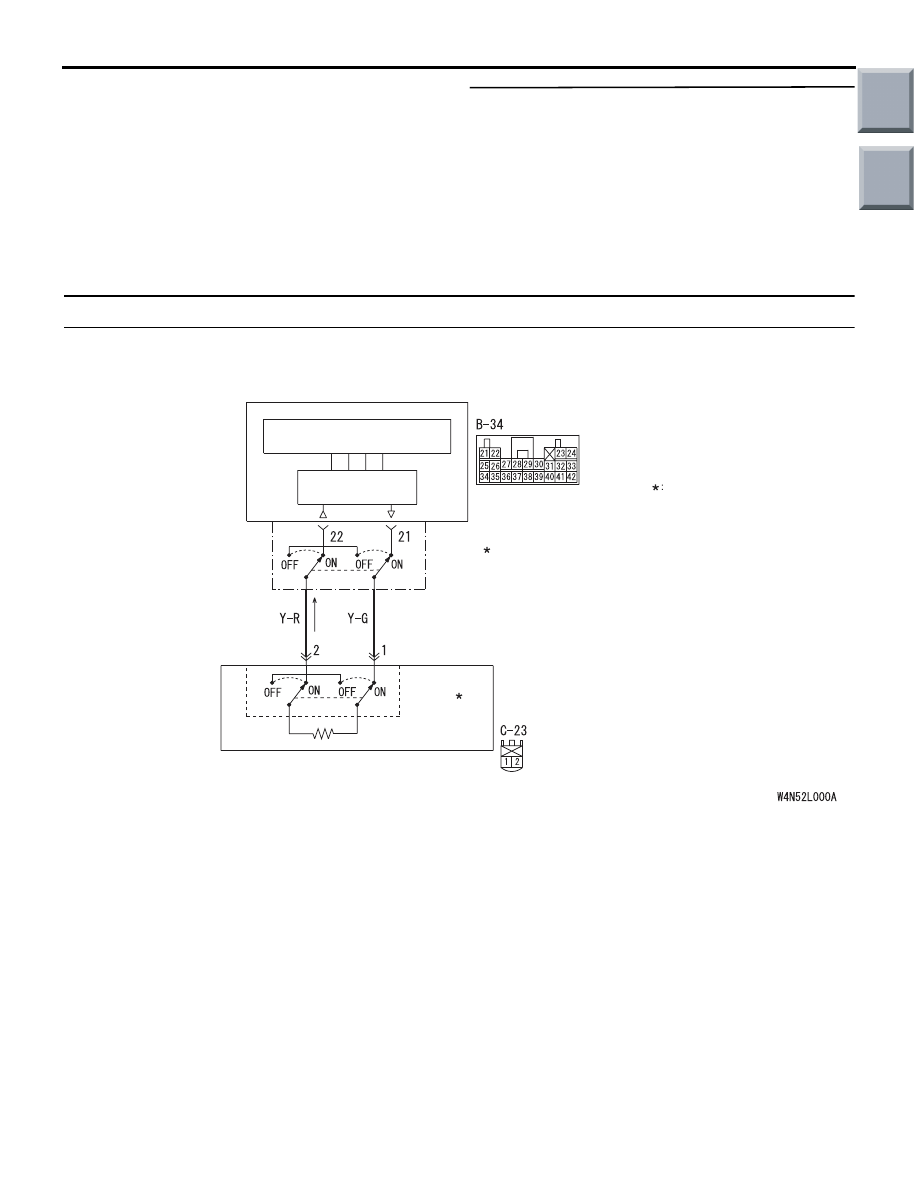
Code No.85: Side-airbag module (squib) (LH) system (short-circuited to the power supply)
OPERATION
• The SRS-ECU judges how severe a collision is
by detecting signals from the left and right side
impact sensors. If the impact is over a predeter-
mined level, the SRS-ECU sends an ignition sig-
nal. At this time, if the side-airbag safing
G-sensor is on, the SRS side-airbag will inflate.
• The ignition signal is input to the side-airbag
module to inflate the side-airbag.
DIAGNOSIS CODE SET CONDITIONS
This diagnosis code is set if the side-airbag squib
(LH) wire(s) are short-circuited to the power supply.
PROBABLE CAUSES
• Damaged wiring harnesses or connectors
• Short to the power supply in the side-airbag mod-
ule (LH) (squib) harness
• Malfunction of the SRS-ECU
AC510246
AIR BAG DRIVE
CIRCUIT
MICRO COMPUTER
SRS-ECU
SIDE-AIRBAG
MODULE
(SQUIB)
(LH)
Wire colour code
B : Black LG : Light green
G : Green L : Blue
W : White Y : Yellow
SB : Sky blue BR : Brown
O : Orange GR : Grey
R : Red P : Pink V : Violet
NOTE
CONNECTOR
COUPLED: ON
CONNECTOR
UNCOUPLED: OFF
CONNECTOR
LOCK
SWITCH
CONNECTOR
LOCK
SWITCH
Side-airbag Module (LH) (Squib) Circuit
AB
Main
Index
Group
TOC
Нет комментариевНе стесняйтесь поделиться с нами вашим ценным мнением.
Текст