Mitsubishi Colt Ralliart. Manual — part 735

TROUBLESHOOTING
MULTIPORT FUEL INJECTION (MPI) <4G1>
13B-265
STEP 2. Perform output wave pattern
measurement of crank angle sensor and
camshaft position sensor (Using an
oscilloscope).
Crank Angle Sensor
• Use special tool test harness (MB991658) to con-
nect A-133 crank angle sensor intermediate con-
nector, and measure at pick-up harness.
• Engine: Idling
• Transmission: Neutral
• Voltage between terminal No. 2 and earth.
Camshaft position sensor
• Use special tool test harness (MB991709) to con-
nect A-110 camshaft position sensor connector,
and measure at pick-up harness.
• Engine: Idling
• Transmission: Neutral
• Voltage between terminal No. 2 and earth.
OK: Output waveform timings of both sen-
sors are the same as the check procedure
(Refer to
) using an oscilloscope.
Q: Is the check result normal?
YES :
Go to Step 3 .
NO :
Go to Step 4 .
STEP 3. Check the trouble symptom.
Q: Does trouble symptom persist?
YES :
Replace engine-ECU.
NO :
Intermittent malfunction (Refer to GROUP
00
− How to Use
Troubleshooting/Inspection Service Points
−
How to Cope with Intermittent Malfunctions
).
STEP 4. Check crank angle sensor and camshaft
position sensor mounted conditions.
Q: Is the check result normal?
YES :
Go to Step 5 .
NO :
Repair.
STEP 5. Check timing marks of timing belt.
Q: Is the check result normal?
YES :
Go to Step 6 .
NO :
Align timing marks.
STEP 6. Check crank angle sensor sensing
blade.
Q: Is the check result normal?
YES :
Go to Step 7 .
NO :
Replace crank angle sensor sensing blade.
STEP 7. Check camshaft position sensing
cylinder.
Q: Is the check result normal?
YES :
Go to Step 8 .
NO :
Replace camshaft position sensing cylinder.
STEP 8. Replace crank angle sensor
• After replacing the crank angle sensor, re-check
the trouble symptoms.
Q: Does trouble symptom persist?
YES :
Go to Step 9 .
NO :
Check end.
STEP 9. Replace camshaft position sensor
• After replacing the camshaft position sensor,
re-check the trouble symptoms.
Q: Does trouble symptom persist?
YES :
Replace engine-ECU.
NO :
Intermittent malfunction (Refer to GROUP
00
− How to Use
Troubleshooting/Inspection Service Points
−
How to Cope with Intermittent Malfunctions
).
AK402095
1
2
3
AC
A-133(DG)
Connector: A-133
Harness side
connector
AK402097
1
2
3
AC
Connector: A-110
Harness side
connector
A-110(B)
Main
Index
Group
TOC

TROUBLESHOOTING
MULTIPORT FUEL INJECTION (MPI) <4G1>
13B-266
Inspection Procedure 15: Run On (Dieseling)
COMMENT ON TROUBLE SYMPTOM
• Failure is possibly caused by leakage from injec-
tor.
PROBABLE CAUSES
• Failed injector
• Failed engine-ECU
DIAGNOSIS PROCEDURE
STEP 1. Check injector for spray condition.
• Check each injector for spray condition (Refer to
).
Q: Is the check result normal?
YES :
Replace engine-ECU.
NO :
Replace injector.
Inspection Procedure 16: Odor, White Smoke, Black Smoke, and High-Concentration CO/HC during
Idling
COMMENT ON TROUBLE SYMPTOM
• Failure is possibly caused by improper air-fuel
ratio, deteriorated catalyst, failed ignition system,
failed fuel system, improper compression pres-
sure, or other faults.
PROBABLE CAUSES
• Failed air-fuel ratio control system
• Failed ignition system
• Failed fuel system
• Failed intake/exhaust system
• Failed exhaust gas cleaning systems
• Improper compression pressure
• Failed catalytic converter
• Failed engine-ECU
DIAGNOSIS PROCEDURE
STEP 1. M.U.T.-III diagnosis code
Q: Is the diagnosis code output?
YES :
Inspection chart for diagnosis code (Refer
to
NO :
Go to Step 2 .
STEP 2. Check injector for operating sound.
• Check injector for operating sound (Refer to
).
Q: Can operating sound be heard?
YES :
Go to Step 3 .
NO :
Check the injector system of the defective
cylinder.
(Refer to Code No. P0201: No. 1 Injector
(Refer to Code No. P0202: No. 2 Injector
(Refer to Code No. P0203: No. 3 Injector
).
(Refer to Code No. P0204: No. 4 Injector
).
STEP 3. Check ignition timing.
• Check ignition timing (Refer to GROUP 11C −
On-vehicle Service
− Ignition Timing Check
Q: Is the check result normal?
YES :
Go to Step 4 .
NO :
Check for offset ignition timing (Refer to
Inspection Procedure 14
Main
Index
Group
TOC

TROUBLESHOOTING
MULTIPORT FUEL INJECTION (MPI) <4G1>
13B-267
STEP 4. M.U.T.-III data list
• Refer to Data List Reference Table
.
a. Item 12: Air flow sensor
b. Item 13: Intake air temperature sensor
c. Item 21: Engine coolant temperature sensor
d. Item 25: Barometric pressure sensor
Q: Are the check results normal?
YES :
Go to Step 5 .
NO :
Perform the diagnosis code classified check
procedure for the sensor that has shown an
abnormal data value (Refer to Inspection
Chart for Diagnosis Code
STEP 5. Check air intake from intake hose and
inlet manifold.
Q: Is the check result normal?
YES :
Go to Step 6 .
NO :
Repair.
STEP 6. Check exhaust manifold for emission
leakage.
Q: Is the check result normal?
YES :
Go to Step 7 .
NO :
Repair.
STEP 7. Check throttle body (throttle valve) for
contamination.
Q: Is the check result normal?
YES :
Go to Step 8 .
NO :
Clean throttle body (throttle valve) (Refer to
).
STEP 8. M.U.T.-III data list
• Refer to Data List Reference Table
.
a. Item 11: Oxygen sensor (front)
b. Item 59: Oxygen sensor (rear)
Q: Is the check result normal?
YES :
Go to Step 9 .
NO :
Perform the diagnosis code classified check
procedure for the sensor that has shown an
abnormal data value (Refer to Inspection
Chart for Diagnosis Code
STEP 9. Check purge control solenoid valve.
• Check purge control solenoid valve (Refer to
GROUP 17
− Emission Control System − Evapo-
rative Emission Control System
− Purge Control
Solenoid Valve Check
Q: Is the check result normal?
YES :
Go to Step 10 .
NO :
Replace purge control solenoid valve.
STEP 10. Fuel pressure measurement.
• Fuel pressure measurement (Refer to Fuel Pres-
sure Test
Q: Is the check result normal?
YES :
Go to Step 11 .
NO :
Repair.
STEP 11. Check positive crankcase ventilation
valve.
• Check positive crankcase ventilation valve (Refer
to GROUP 17
− Emission Control System −
Crankcase Emission Control System
− Positive
Crankcase Ventilation (PCV) Valve Check
).
Q: Is the check result normal?
YES :
Go to Step 12 .
NO :
Replace positive crankcase ventilation
valve.
STEP 12. Visual check of ignition spark.
• Remove the spark plug and install it to the ignition
coil.
• Connect the ignition coil connector.
• Remove all injector connector.
• At the engine start, check each spark plug pro-
duces a spark.
Q: Is the check result normal?
YES :
Go to Step 14 .
NO :
Go to Step 13 .
STEP 13. Check spark plug.
• Check spark plug (Refer to GROUP 16 − Ignition
System
− On-vehicle Service
).
Q: Is the check result normal?
YES :
Check ignition circuit system (Refer to
Inspection Procedure 26
NO :
Replace spark plug.
Main
Index
Group
TOC
TROUBLESHOOTING
MULTIPORT FUEL INJECTION (MPI) <4G1>
13B-268
STEP 14. Check compression pressure.
• Check compression pressure (Refer to GROUP
11C
− On-vehicle Service − Compression Pres-
sure Check
Q: Is the check result normal?
YES :
Go to Step 15 .
NO :
Repair.
STEP 15. Check injector for spray condition.
• Check each injector for spray condition (Refer to
).
Q: Is the check result normal?
YES :
Go to Step 16 .
NO :
Replace injector.
STEP 16. Replace catalytic converter
• After replacing the catalytic converter, re-check
the trouble symptoms.
Q: Does trouble symptom persist?
YES :
Replace engine-ECU.
NO :
Check end.
Inspection Procedure 17: Battery Run Down
COMMENT ON TROUBLE SYMPTOM
• Failure is possibly caused by failed alternator,
failed power generation control system, or other
faults.
PROBABLE CAUSES
• Failed battery
• Alternator G terminal short-circuited
• Failed alternator
• Failed engine-ECU
DIAGNOSIS PROCEDURE
STEP 1. Check battery voltage.
• Measure battery voltage during cranking
OK: 8 V or more
Q: Is the check result normal?
YES :
Go to Step 2 .
NO :
Check battery (Refer to GROUP 54A
−
Battery
− On-vehicle Service − Battery Test
).
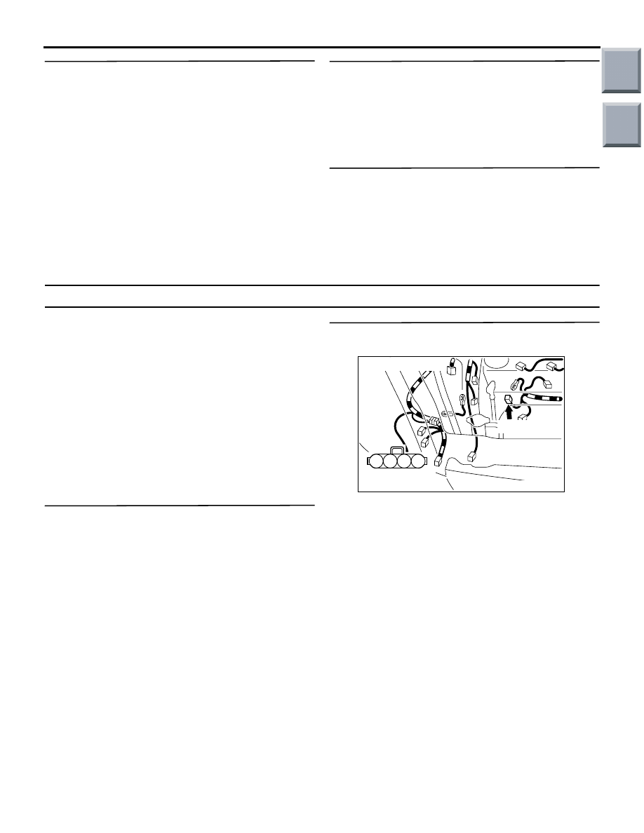
STEP 2. Connector check: A-131 alternator
connector
Q: Is the check result normal?
YES :
Go to Step 3 .
NO :
Repair or replace.
2
1
3
4
AK402098
A-131(G)
Connector: A-131
Harness side
connector
AC
Main
Index
Group
TOC
Нет комментариевНе стесняйтесь поделиться с нами вашим ценным мнением.
Текст