Mitsubishi Colt Ralliart. Manual — part 733

TROUBLESHOOTING
MULTIPORT FUEL INJECTION (MPI) <4G1>
13B-257
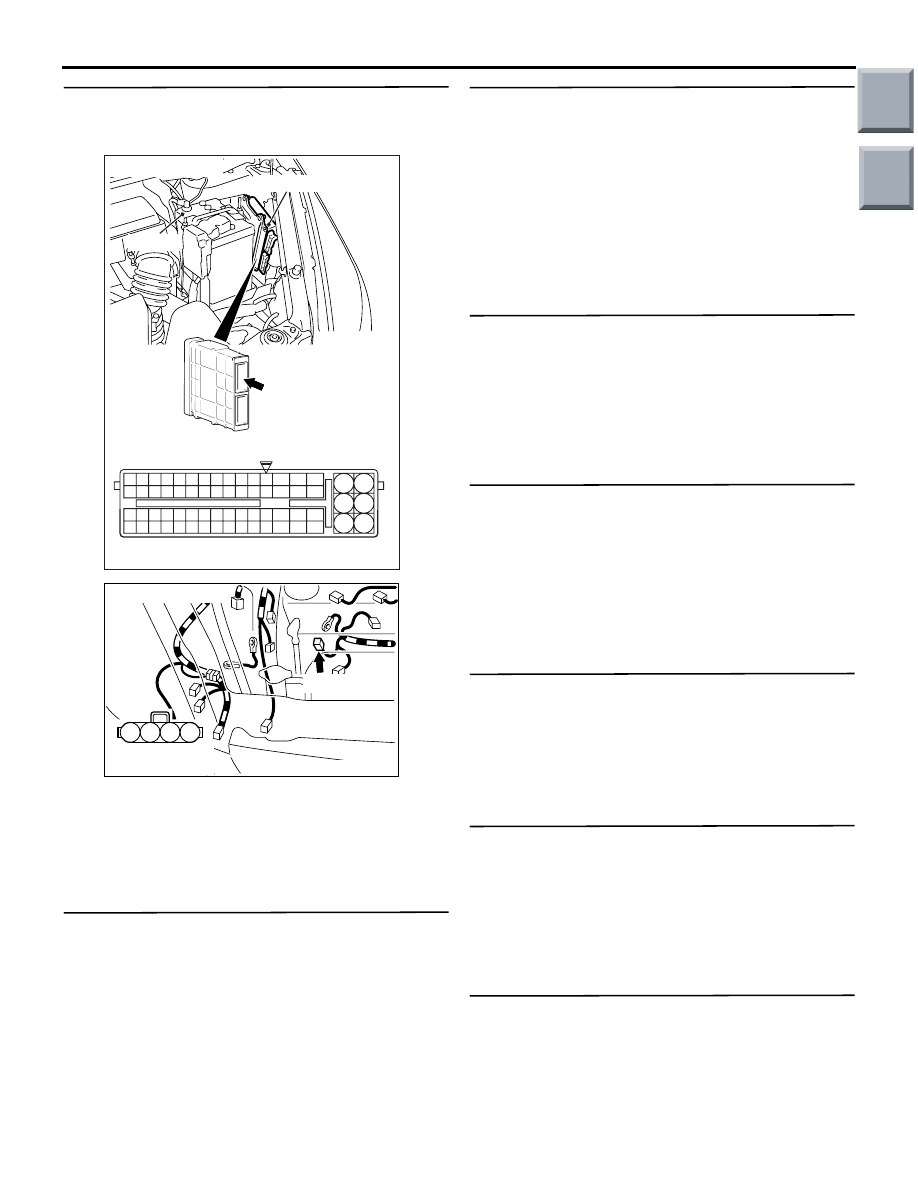
STEP 9. Perform voltage measurement at A-114
engine-ECU connector.
• Disconnect engine-ECU connector, and connect
Special Tool Power Plant ECU Check Harness
(MB991987), and then measure the voltage on
the check connector.
• Engine: Idling after warm-up
• Transmission: Neutral
• Radiator fan: Not operating
• Voltage between terminal No. 64 and earth.
OK: Switching the headlamps to ON from
OFF causes the voltage to increase 0.2
− 3.5
V.
Q: Is the check result normal?
YES :
Go to Step 13 .
NO :
Go to Step 10 .
STEP 10. Connector check: A-114 engine-ECU
connector and A-131 alternator connector
Q: Is the check result normal?
YES :
Go to Step 11 .
NO :
Repair or replace.
AK402745
6
4
2
5
3
1
9
7
8
10
11
12
13
14
15
16
17
18
19
20
21
22
23
24
25
26
27
28
29
30
31
32
33
34
35
36
37
38
39
40
41
42
43
44
45
46
47
48
49
50
51
52
53
54
55
56
57
58
59
60
61
62
63
64
65
66
L
AF
A-114
Connector:
A-114
Harness side connector
Engine-ECU
Battery
AK402745
6
4
2
5
3
1
9
7
8
10
11
12
13
14
15
16
17
18
19
20
21
22
23
24
25
26
27
28
29
30
31
32
33
34
35
36
37
38
39
40
41
42
43
44
45
46
47
48
49
50
51
52
53
54
55
56
57
58
59
60
61
62
63
64
65
66
L
AF
A-114
Connector:
A-114
Harness side connector
Engine-ECU
Battery
2
1
3
4
AK402098
A-131(G)
Connector: A-131
Harness side
connector
AC
Main
Index
Group
TOC
TROUBLESHOOTING
MULTIPORT FUEL INJECTION (MPI) <4G1>
13B-258
STEP 11. Check harness between A-114 (terminal
No. 64) engine-ECU connector and A-131
(terminal No. 1) alternator connector.
• Check output line for open/short circuit or dam-
age.
Q: Is the check result normal?
YES :
Go to Step 12 .
NO :
Repair.
STEP 12. Check the trouble symptom.
Q: Does trouble symptom recur?
YES :
Replace alternator.
NO :
Intermittent malfunction (Refer to GROUP
00
− How to Use
Troubleshooting/Inspection Service Points
−
How to Cope with Intermittent Malfunctions
).
STEP 13. Visual check of ignition spark.
• Remove the spark plug and install it to the ignition
coil.
• Connect the ignition coil connector.
• Remove all injector connector.
• At the engine start, check each spark plug pro-
duces a spark.
Q: Is the check result normal?
YES :
Go to Step 15
NO :
STEP 14. Check spark plug.
• Check spark plug (Refer to GROUP 16 − Ignition
System
− On-vehicle Service
).
Q: Is the check result normal?
YES :
Check ignition circuit system (Refer to
Inspection Procedure 26
NO :
Replace spark plug.
STEP 15. Check purge control solenoid valve.
• Check purge control solenoid valve (Refer to
GROUP 17
− Emission Control System − Evapora-
tive Emission Control System
− Purge Control
Solenoid Valve Check
Q: Is the check result normal?
YES :
Go to Step 16 .
NO :
Replace purge control solenoid valve.
STEP 16. Check injector for spray condition.
• Check each injector for spray condition (Refer to
).
Q: Is the check result normal?
YES :
Go to Step 17 .
NO :
Replace injector.
STEP 17. Check compression pressure.
• Check compression pressure (Refer to GROUP
11C
− On-vehicle Service − Compression Pressure
Check
).
Q: Is the check result normal?
YES :
Go to Step 18 .
NO :
Repair.
STEP 18. Replace engine-ECU
• After engine-ECU is replaced, re-check for trou-
ble symptom.
Q: Does trouble symptom recur?
YES :
Check for foreign matters (water, kerosene,
etc.) in fuel and replace if necessary.
NO :
Check end.
AK402745
6
4
2
5
3
1
9
7
8
10
11
12
13
14
15
16
17
18
19
20
21
22
23
24
25
26
27
28
29
30
31
32
33
34
35
36
37
38
39
40
41
42
43
44
45
46
47
48
49
50
51
52
53
54
55
56
57
58
59
60
61
62
63
64
65
66
L
AF
A-114
Connector:
A-114
Harness side connector
Engine-ECU
Battery
2
1
3
4
AK402098
A-131(G)
Connector: A-131
Harness side
connector
AC
Main
Index
Group
TOC

TROUBLESHOOTING
MULTIPORT FUEL INJECTION (MPI) <4G1>
13B-259
Inspection Procedure 8: The Engine Stalls when Starting the Car (Pass Out)
COMMENT ON TROUBLE SYMPTOM
• Engine stall on starting is possibly caused by mis-
fire due to failed spark plug, improper air-fuel
ratio at accelerator pedal depression, or other
faults.
• Engine stall on deceleration is possibly caused by
improper air-fuel ratio due to lack of intake air or
failed EGR system.
PROBABLE CAUSES
• Failed ignition system
• Failed intake system
• Failed emission gas cleaning system
• Throttle valve fouled around
• Failed engine-ECU
DIAGNOSIS PROCEDURE
STEP 1. M.U.T.-III diagnosis code
Q: Is the diagnosis code output?
YES :
Inspection chart for diagnosis code (Refer
to
NO :
Go to Step 2 .
STEP 2. M.U.T.-III data list
• Refer to Data List Reference Table
.
a. Item 14: Throttle position sensor (sub)
b. Item 77: Accelerator pedal position sensor
(sub)
c. Item 78: Accelerator pedal position sensor
(main)
d. Item 79: Throttle position sensor (main)
Q: Are the check results normal?
YES :
Go to Step 3 .
NO :
Perform the diagnosis code classified check
procedure for the sensor that has shown an
abnormal data value (Refer to Inspection
Chart to Diagnosis Code
).
STEP 3. Check air intake from intake hose and
inlet manifold.
Q: Is the check result normal?
YES :
Go to Step 4 .
NO :
Repair.
STEP 4. Check throttle body (throttle valve) for
contamination.
Q: Is the check result normal?
YES :
Go to Step 5 .
NO :
Clean throttle body (throttle valve) (Refer to
).
STEP 5. Visual check of ignition spark.
• Remove the spark plug and install it to the ignition
coil.
• Connect the ignition coil connector.
• Remove all injector connector.
• At the engine start, check each spark plug pro-
duces a spark.
Q: Is the check result normal?
YES :
Replace engine-ECU.
NO :
Go to Step 6 .
STEP 6. Check spark plug.
• Check spark plug (Refer to GROUP 16 − Ignition
System
− On-vehicle Service
).
Q: Is the check result normal?
YES :
Check ignition circuit system (Refer to
Inspection Procedure 26
NO :
Replace spark plug.
Main
Index
Group
TOC

TROUBLESHOOTING
MULTIPORT FUEL INJECTION (MPI) <4G1>
13B-260
Inspection Procedure 9: Engine Does Not Revole Up
COMMENT ON TROUBLE SYMPTOM
• Failure is possibly caused by failed electronically
controlled throttle valve system, fuel system, igni-
tion system, or other faults.
PROBABLE CAUSES
• Failed ignition system
• Failed fuel system
• Failed electronically controlled throttle valve sys-
tem
• Incorrectly installed timing belt
• Failed engine-ECU
DIAGNOSIS PROCEDURE
STEP 1. M.U.T.-III diagnosis code
Q: Is the diagnosis code output?
YES :
Inspection chart for diagnosis code (Refer
to
NO :
Go to Step 2 .
STEP 2. M.U.T.-III data list
• Refer to Data List Reference Table
.
a. Item 14: Throttle position sensor (sub)
b. Item 77: Accelerator pedal position sensor
(sub)
c. Item 78: Accelerator pedal position sensor
(main)
d. Item 79: Throttle position sensor (main)
Q: Are the check results normal?
YES :
Go to Step 3 .
NO :
Perform the diagnosis code classified check
procedure for the sensor that has shown an
abnormal data value (Refer to Inspection
Chart to Diagnosis Code
).
STEP 3. Check timing marks of timing belt.
Q: Is the check result normal?
YES :
Go to Step 4 .
NO :
Align timing marks.
STEP 4. Visual check of ignition spark.
• Remove the spark plug and install it to the ignition
coil.
• Connect the ignition coil connector.
• Remove all injector connector.
• At the engine start, check each spark plug pro-
duces a spark.
Q: Is the check result normal?
YES :
Go to Step 6 .
NO :
Go to Step 5 .
STEP 5. Check spark plug.
• Check spark plug (Refer to GROUP 16 − Ignition
System
− On-vehicle Service
).
Q: Is the check result normal?
YES :
Check ignition circuit system (Refer to
Inspection Procedure 26
NO :
Replace spark plug.
STEP 6. Fuel pressure measurement.
• Fuel pressure measurement (Refer to Fuel Pres-
sure Test
Q: Is the check result normal?
YES :
Replace engine-ECU.
NO :
Repair.
Main
Index
Group
TOC
Нет комментариевНе стесняйтесь поделиться с нами вашим ценным мнением.
Текст