Mitsubishi Colt Ralliart. Manual — part 35

TROUBLESHOOTING
MULTIPORT FUEL INJECTION (MPI) <4A9>
13A-94
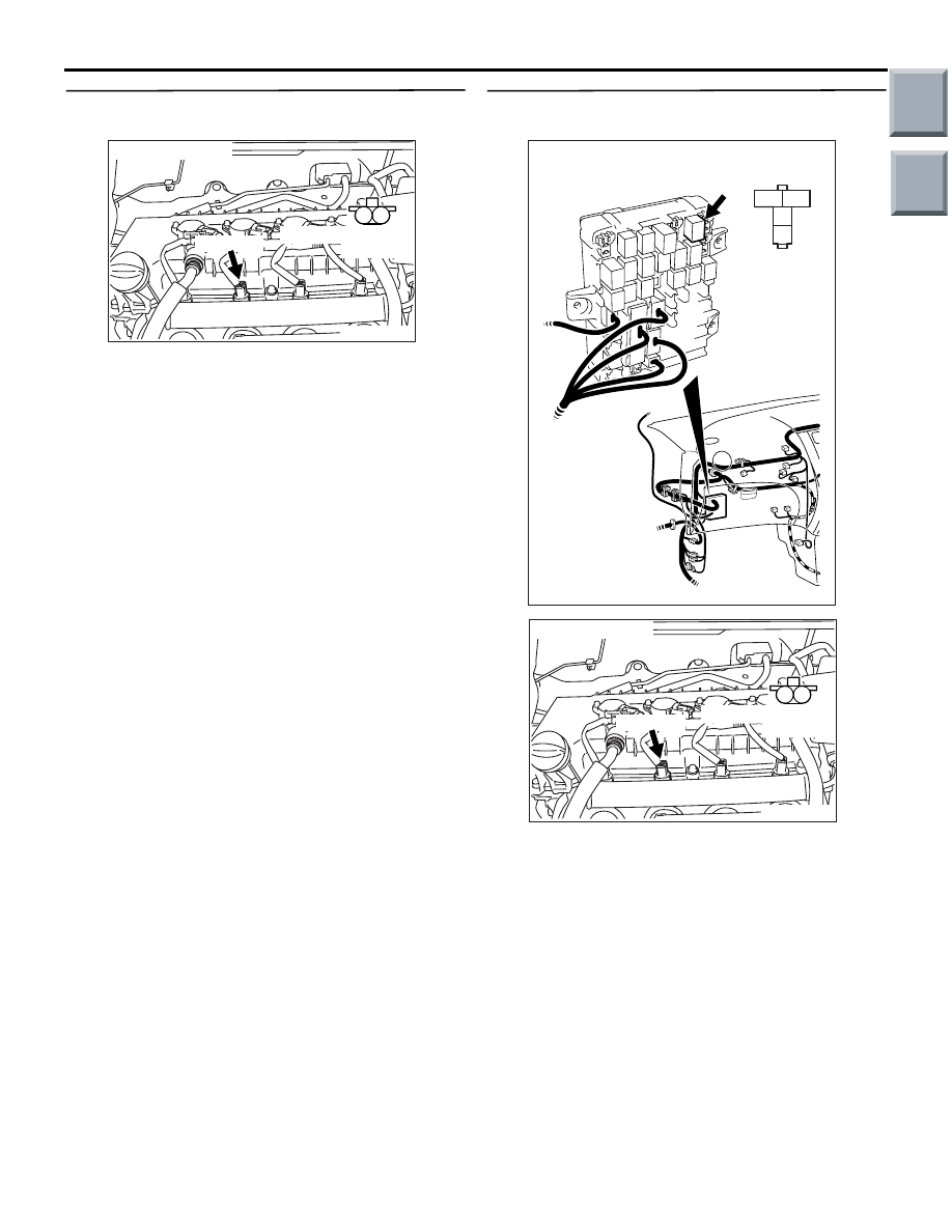
Code No. P0202: No. 2 Injector System
AK402684
2
1
3
1
2
4
19
21
20
18
17
16
15
14
1213
11
8 9
L
10
37
52 53 54 555657585960616263646566
38 39 404142434445464748495051
22 23 24 252627282930313233343536
7
5
3
1
6
4
2
A-114
AK
B-106
A-17
B-112
B-108
Engine
control
relay
Injector
No. 2
A-103
(MU802062)
4
6
4
1
2
2
9
No. 2 Injector Circuit
R
R
Y-R
3
1
1
1
R
Fusible link
16
20A
J/B
To engine-ECU <M/T> or
engine-CVT-ECU <CVT>
Engine-ECU <M/T> or
engine-CVT-ECU <CVT>
Wire colour code
B: Black LG: Light green G: Green L: Blue W: White Y: Yellow SB: Sky blue BR: Brown O: Orange GR: Gray
R: Red P: Pink V: Violet Pu: Purple
Main
Index
Group
TOC

TROUBLESHOOTING
MULTIPORT FUEL INJECTION (MPI) <4A9>
13A-95
OPERATION
• Power is supplied to the injector (terminal No. 1)
from the engine control relay (terminal No. 4).
• The engine-ECU connector or engine-CVT-ECU
connector (terminal No. 9) makes the power tran-
sistor in the unit be in ON position, and that
makes currents go on the injector (terminal No.
2).
FUNCTION
• The engine-ECU <M/T> or engine-CVT-ECU
<CVT> controls the power supply interval of the
injector.
• The fuel injection amount of the injector depends
on the power supply interval.
TROUBLE JUDGMENT
Check Conditions
• Engine speed is between 50 and 1,000 r/min.
• Throttle position sensor (main) output is 1.0 V or
less.
• Injector operation (by carrying out actuator test)
is not in progress.
Judgment Criterion
• Injector coil surge voltage (battery positive volt-
age +2 V) has not been detected for 4 seconds.
PROBABLE CAUSES
• Failed No. 2 injector
• Open/short circuit in No. 2 injector circuit or loose
connector contact
• Failed engine-ECU <M/T> or engine-CVT-ECU
<CVT>
DIAGNOSIS PROCEDURE
STEP 1. M.U.T.-III actuator test
• Item 02: No. 2 injector
OK: Idling state varies.
Q: Is the check result normal?
YES :
Intermittent malfunction (Refer to GROUP
00
− How to Use
Troubleshooting/Inspection Service Points
−
How to Cope with Intermittent Malfunctions
).
NO :
Go to Step 2 .
STEP 2. Connector check: A-103 No. 2 injector
connector
Q: Is the check result normal?
YES :
Go to Step 3 .
NO :
Repair or replace the connector.
STEP 3. Perform resistance measurement at
A-103 No. 2 injector connector.
• Disconnect connector, and measure at injector
side.
• Resistance between terminal No. 1 and No. 2.
OK: 14
− 15 Ω (at 20°C)
Q: Is the check result normal?
YES :
Go to Step 4 .
NO :
Replace No. 2 injector.
AK402148
M
1
2
A-103 (G)
Connector: A-103
AC
A-103 Harness side
connector
AK402165
1 2
A-103 (G)
Connector: A-103
AC
A-103 Equipment side
connector
Main
Index
Group
TOC
TROUBLESHOOTING
MULTIPORT FUEL INJECTION (MPI) <4A9>
13A-96
STEP 4. Perform voltage measurement at A-103
No. 2 injector connector.
• Disconnect connector, and measure at harness
side.
• Ignition switch: ON
• Voltage between terminal No. 1 and earth.
OK: System voltage
Q: Is the check result normal?
YES :
Go to Step 6 .
NO :
Go to Step 5 .
STEP 5. Connector check: B-106 engine control
relay connector
Q: Is the check result normal?
YES :
Check intermediate connector A-17 and
B-112, and repair if necessary. If
intermediate connectors are normal, check
and repair harness between B-106 (terminal
No. 4) engine control relay connector and
A-103 (terminal No. 1) No. 2 injector
connector.
• Check power supply line for
open/short circuit.
NO :
Repair or replace the connector.
AK402148
M
1
2
A-103 (G)
Connector: A-103
AC
A-103 Harness side
connector
3
2
1
4
AK402060
B-106
J/B side
connector
B-106
Connector: B-106
J/B (front side)
AC
AK402148
M
1
2
A-103 (G)
Connector: A-103
AC
A-103 Harness side
connector
Main
Index
Group
TOC

TROUBLESHOOTING
MULTIPORT FUEL INJECTION (MPI) <4A9>
13A-97
STEP 6. Connector check: A-114 engine-ECU
connector or engine-CVT-ECU connector
Q: Is the check result normal?
YES :
Go to Step 7 .
NO :
Repair or replace the connector.
STEP 7. Check harness between B-106 (terminal
No. 4) engine control relay connector and A-103
(terminal No. 1) No. 2 injector connector.
NOTE: Before checking harness, check intermediate
connectors A-17 and B-112, and repair if necessary.
• Check power supply line for damage.
Q: Is the check result normal?
YES :
Go to Step 8 .
NO :
Repair the damaged harness wire.
AK402745
6
4
2
5
3
1
9
7
8
10
11
12
13
14
15
16
17
18
19
20
21
22
23
24
25
26
27
28
29
30
31
32
33
34
35
36
37
38
39
40
41
42
43
44
45
46
47
48
49
50
51
52
53
54
55
56
57
58
59
60
61
62
63
64
65
66
L
AD
A-114
Connector:
A-114
Harness side connector
Engine-ECU <M/T> or
engine-CVT-ECU <CVT>
Battery
3
2
1
4
AK402060
B-106
J/B side
connector
B-106
Connector: B-106
J/B (front side)
AC
AK402148
M
1
2
A-103 (G)
Connector: A-103
AC
A-103 Harness side
connector
Main
Index
Group
TOC
Нет комментариевНе стесняйтесь поделиться с нами вашим ценным мнением.
Текст